21
DPLLD Field Wiring
Refer to the appropriate Site Prep manual (P/N 577014-073 - TLS-450PLUS or P/N 577013-
879 TLS-450) for required wiring types/lengths for pressure transducer and pump control
field wiring.
DPLLD Transducers
Disconnect, lock out, and tag all AC power to the TLS console,
dispensers and submersible pumps.
1. Pull a shielded, 2-conductor cable from each DPLLD transducer’s sump junction box to the appropriate USM
module in the TLS console. NOTE: The transducer is an intrinsically safe device and its wiring must not share
a conduit with any non-intrinsically safe device.
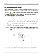
2. Using wire nuts, connect the white and black wires from the DPLLD transducer to field wires in the
weatherproof sump junction box (ref. Figure
17).
Be sure to maintain correct polarity between the color-
coded or marked field wires and DPLLD transducer wires when making all connections. Cut off
the transducer shielded ground wire (if present) flush with the cable jacket. Do the same for the
cable shield.
The shielded cable drain wire must be connected to the ground lug in the intrinsically safe
area of the console, not to the transducer!
Figure 17. Field Connections Of DPLLD Transducer
3. Seal wire nut connections using the epoxy sealant furnished with each transducer. Use one packet for no more
than two wire nut connections.
Ensure the end of the cable jacket is submerged in the epoxy.
Refer to
18 as you prepare epoxy and seal connections.
Do not put more than two wire nut connections in one epoxy sealant bag or the
connections will not be properly sealed. Improper sealing of the connections will result
in inaccurate system readings and possibly false alarms.


