background image

92

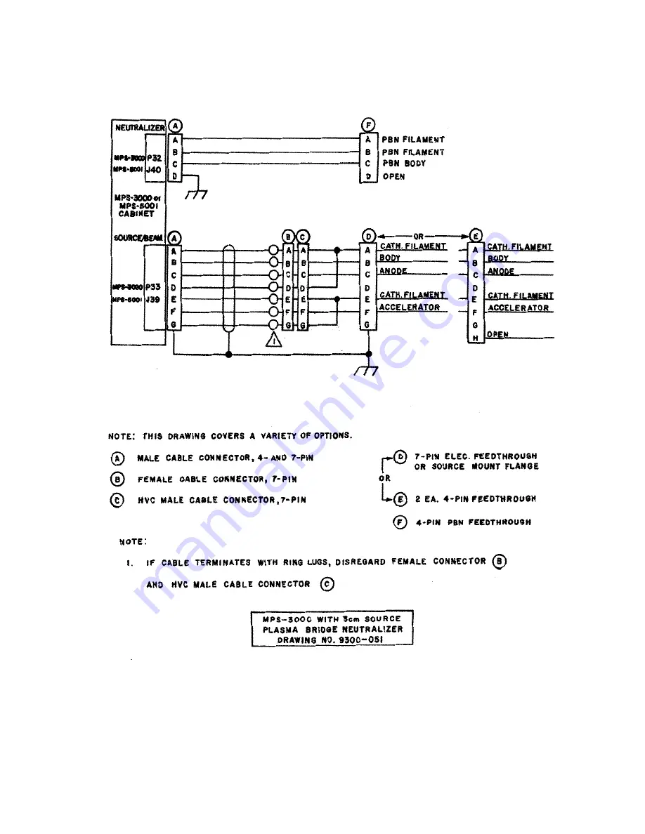
3cm Source Plasma Bridge Neutralizer

Содержание MPS-3000 CE

Страница 1: ...MPS 3000 CE Power Supply Technical Manual 425964...

Страница 2: ...MPS 3000 CE Power Supply Technical Manual...

Страница 3: ...the policy of Veeco Instruments Inc to improve products as new technology components and materials become available Veeco Instruments Inc therefore reserves the right to change specifications without...

Страница 4: ...ns 74 Tables 83 Environmental Safety 84 Drawings 85 Filament Cathode with Filament Neutralizer or PBN Option 86 Hollow Cathode and HCN 7 pin or 2 x 4 pin feedthrough 87 Hollow Cathode and Hollow Catho...

Страница 5: ...low these words to avoid possible injury or death This symbol marks an imminent hazard which will kill or injure if ignored This symbol marks a potential hazard which may kill or injure if ignored Thi...

Страница 6: ...dware interlocks are working Keep all guards and panels in place during routine system operation Complete ion beam systems from Veeco Instruments Inc are supplied with hardware interlocks and software...

Страница 7: ...configuration ensures that the user accessible EIA 232 and system interlock circuits remain at Safety Extra Low Voltage SELV under normal and single fault conditions The customer side supply 5V DC is...

Страница 8: ...ht be adjusted up or down as required depending upon the size and type of filament wire used Operate in Manual Local Local Restricted or Remote mode Manual Mode Each of the individual power supplies i...

Страница 9: ...in Remote mode By using an EIA 2321 interface a computer may control power supplies and may recall conditions from memory The MEMORY MODULE and FUNCTION select switches are nonfunctional in Remote mo...

Страница 10: ...e located in the sides of the chassis and the cooling fan port is located in the rear panel of the chassis 2 Connect the following a The source beam cable to the source beam connector P33 located on t...

Страница 11: ...rear panel is in the OFF position 5 Connect the unit s line cord to an appropriate power source See Specifications on page 74 If connecting to a three wire power service with two hot lines and facili...

Страница 12: ...ppear throughout to identify the power supply s controls as their use and function is referenced FIGURE 4 1 Front Panel MPS 3000 CE FC 1 2 3 4 5 6 9 7 10 8 14 13 15 16 17 18 19 12 11 FIGURE 4 2 Front...

Страница 13: ...ament Current Display 6 Memory 19 Not used 7 Module 20 HC Heater Current Display 8 Function 21 HC Keeper Voltage Display 9 Adjust 22 HCN Emission Heater Cur rent Display 10 Cathode Filament Current Di...

Страница 14: ...ord SOURCE appears above the switch indicating the SOURCE switch has been selected The SOURCE switch may be turned off in any mode While in Remote mode the SOURCE switch may be turned on through the r...

Страница 15: ...has been selected Local Only the following parameters may be adjusted beam voltage beam current accelerator voltage and A B Ratio when in Local mode All remaining parameters may not be changed from t...

Страница 16: ...that are stored in memory The MEMORY switch is active in all modes except Remote MEM 1 When the number 1 appears above the MEMORY switch the power supply will operate from memory location one When any...

Страница 17: ...e Discharge The letters DISCHRG appear above the MODULE switch indicating that Discharge power supply has been selected MPS 3000 CE FC PBN and HC The discharge current limit may be selected and adjust...

Страница 18: ...anual mode and through a computer HCN The HCN power supply is part of the MPS 3000 CE HC The letters HCN appear above the MODULE switch indicating that Hollow Cathode Neutralizer power supply has been...

Страница 19: ...thode or PBN power supply has been selected The beam current may be selected when operating in Local mode The word CURRENT appears above the FUNCTION switch indicating that beam current has been selec...

Страница 20: ...he knob is not being turned Anytime the knob is turned the new value is stored automati cally in the selected memory Cathode Filament Current Display 10 Indicates the amount of current supplied from t...

Страница 21: ...llow cathode HC Keeper Voltage Display 21 Indicates the amount of keeper voltage necessary for the operation of the internal hollow cathode or shows the setting of the keeper voltage limit When the le...

Страница 22: ...ed PBN Emission Filament Current Display 24 Indicates one of two parameters emission current or filament current The display will show emission current unless PBN and LIMIT have been selected by the M...

Страница 23: ...CB1 4 Primary circuit breaker for the input power Body Fuse F9 5 This fuse protects circuitry from positive high voltage to ground shorts Cooling Fan 6 Circulates air through the entire chassis of th...

Страница 24: ...er to Replacing the Switches on page 68 The on position indicates that the switch is towards the top of the board The off position indicates that the switch is towards the bottom of the board Switch S...

Страница 25: ...all other displays will be dark The SOURCE and BEAM switches will be inoperative until the neutralizer fault has been corrected and the power has been cycled MPS 3000 CE HC and PBN On In the on positi...

Страница 26: ...and should never be changed Switch Settings for Switch Bank 2 SW2 1 Not used SW2 2 Controller Board Alarm Switch On In the on position the controller board alarm will sound when a Fatal error has bee...

Страница 27: ...ition will last about one second The controller will self test each of the power supplies from right to left A power supply has been tested when the letter P appears in the top display c A click will...

Страница 28: ...IMIT appears above the switch c Enter the chosen value by turning the Adjust knob The pro grammed value appears on the Discharge Current display d As the Adjust knob is turned the discharge current li...

Страница 29: ...MODULE switch The word NEUTRALIZER appears above the switch b Select Limit with the FUNCTION switch The word LIMIT appears above the switch c Adjust the current limit upwards or downwards as needed Th...

Страница 30: ...voltage will decrease to the pro grammed value b Increase the cathode current if necessary 1 Select the Cathode power supply with the MODULE switch and Current with the FUNCTION switch 2 Turn the Adj...

Страница 31: ...recommended and factory set A B Ratio is 10 for all sources a Select the Accelerator power supply with the MODULE switch The letters ACCEL appear above the switch b Select the A B Ratio with the FUNCT...

Страница 32: ...24 If the chosen beam current requires an increase in cathode filament cur rent carefully monitor this filament current to ensure that it does not exceed the recommended values of 6 5A for 5cm or smal...

Страница 33: ...the Accelerator Current display Operating the ion source with high accelerator current may damage the grids 3 Adjust the neutralizer filament current until the neutralizer emission cur rent is about...

Страница 34: ...about one second The controller will self test each of the power supplies from right to left A power supply has been tested when the letter P appears in the top display c A click will be heard when t...

Страница 35: ...The words DISCHARG and CURRENT appear above the appropriate switches b Enter the chosen value by turning the Adjust knob The pro grammed value appears on the Discharge Current display c As the Adjust...

Страница 36: ...dis play c As the Adjust knob is turned the emission current is entered auto matically into the selected memory location 9 Apply power to the source To avoid electrical shock keep clear of live circui...

Страница 37: ...age display d The final selected A B Ratio is stored automatically in the memory as indicated above the MEMORY switch 12 Select the accelerator voltage For initial start up purposes use a value of 250...

Страница 38: ...tions and or gas flow rate to bring the A B Ratio within the recommended limits When the accelerator current to beam current ratio exceeds the pro grammed A B Ratio value an audio alarm will sound if...

Страница 39: ...mains breaker and the unit s POWER switch on the power supply front to the on position a The fan will start b Random displays will appear and the audio alarm will sound This condition lasts about one...

Страница 40: ...HARG appears above the switch b Select Limit with the FUNCTION switch The word LIMIT appears above the switch c Enter the chosen value by turning the Adjust knob The pro grammed value appears on the D...

Страница 41: ...ct the PBN power supply with the MODULE switch The letters PBN appear above the switch b Select Limit with the FUNCTION switch The word LIMIT appears above the switch c Adjust the current limit up or...

Страница 42: ...oltage will decrease to the pro grammed value c Increase the cathode current if necessary 1 Select the cathode power supply with the MODULE switch and current with the FUNCTION switch 2 Turn the Adjus...

Страница 43: ...ended and factory set A B Ratio is 10 for all sources a Select the Accelerator power supply with the MODULE switch The letters ACCEL appear above the switch b Select the A B Ratio with the FUNCTION sw...

Страница 44: ...sen beam current requires an increase in cathode filament cur rent carefully monitor this filament current to ensure it does not exceed the recommended values of 6 5A for 5cm and smaller sources If th...

Страница 45: ...ed An E25 error message will appear on the Accelerator Current display Operating the ion source with a high accelerator current could damage the grids 3 Adjust the neutralizer emission current until t...

Страница 46: ...ns on page 20 MPS 3000 CE HC In Local mode the internal microprocessor constantly monitors the beam current and maintains it at the programmed value by making adjustments to the discharge current The...

Страница 47: ...nt as a new filament to start or function MPS 3000 CE FC The cathode filament current will ramp to the programmed value The neutralizer filament current will ramp to the value from memory When the neu...

Страница 48: ...condition 7 Wait for the discharge voltage and or current to stabilize 8 Press the BEAM switch The word BEAM should appear above the MODULE switch 9 The beam current beam voltage and accelerator volt...

Страница 49: ...ns in advance 1 Select the chosen operating conditions in Manual or Local mode 2 Select the LOC RES mode with the MODE switch 3 Turn the KEYLOCK switch to the disable position and remove the key 4 The...

Страница 50: ...will be needed for successful connection and communication with the computing device serial communications rate 9600 baud The serial communications rate may be adjusted using switches SW1 5 and SW1 6...

Страница 51: ...ter rate are placed in a 250 character buffer When this buffer is filled additional characters will be lost The RS 232 communications is active in all modes Refer to Command Summary Table on page 48 R...

Страница 52: ...ischarge Current Limit DT Set Discharge Current Threshold DV Set Discharge Voltage M Set Power Supply Mode NE Enable Disable E B Ratio Error NI Set Neutralizer Current NK Enable Disable Front Panel NL...

Страница 53: ...ption This command enables AC1 or disables AC0 the Auto Cathode AC mode which is active only when the power supply is in Remote mode However the command will be accepted in any mode MPS 3000 CE FC PBN...

Страница 54: ...E n cr Units N A Range n 0 or 1 Description This command is used to enable AE1 or disable AE0 auto matic error logging When enabled the power supply will transmit any error conditions that occur while...

Страница 55: ...an one second the beam will be turned off and an E13 error message will appear in the beam current display To disable this feature send the following command to the power sup ply BE0 cr Set the beam c...

Страница 56: ...0 20 00 MPS 3000 CE HC N A Description MPS 3000 CE FC and PBN Used to set the cathode filament current target The filament current will ramp to this value when the power supply is in Manual mode In al...

Страница 57: ...CL5 50 cr Set the MPS 3000 CE HC hollow cathode keeper voltage limit to 25V using the following command CL25 cr Command Name SET DISCHARGE CURRENT Syntax DI n cr Units amperes Range n 0 00 6 00 Descri...

Страница 58: ...RESHOLD Syntax DT n cr Units amperes Range n 0 00 6 00 MUST BE IN THE FORM n nn Description Sets the discharge current threshold value Refer to the auto cathode command for a description of the discha...

Страница 59: ...ctivated if the emission current drops below the beam current In all modes except Manual mode the emission current will still automatically servo to 125 of the beam current When enabled NE0 the E B Ra...

Страница 60: ...ted Set the MPS 3000 CE FC neutralizer filament current target to 4 50A using the following command NI4 50 cr Set the MPS 3000 CE HCN PBN emission current to 250mA using the fol lowing command NI250 c...

Страница 61: ...to set the HCN keeper voltage limit Set the MPS 3000 CE FC PBN neutralizer limit to 5 50A using the follow ing command NL5 50 cr Set the MPS 3000 CE HCN keeper voltage limit to 25V using the following...

Страница 62: ...thode Current HC Heater Current MPS 3000 CE FC MPS 3000 CE HC Amps Amps BB BB Discharge Current All Amps CCC C Discharge Voltage All Volts DDDD Beam Current All mA EEEE Beam Voltage All Volts FFFF Acc...

Страница 63: ...logging parameters without header infor mation If a value is off it will be replaced with ASCII blank spaces 32 Parameter Model Units AA BB CC Time since source was turned on Hours Minutes Seconds DD...

Страница 64: ...XX A XX XX A XXX X V lf cr eot MPS 3000 CE HC lf cr MEM 1 PARAMETERS lf cr BEAM V BEAM I ACCEL V A B RATIO CATH LIM NEUT LIM lf cr XXXX V XXX mA XXXX V XX XXX V XXX V lf cr eot ASCII BLANK SPACE 32 D...

Страница 65: ...s AAAAA Beam Voltage All Volts BBBBB Beam Current All mA CCCCC Accelerator Voltage All Volts DDDDD A B Ratio All EEEEE Cathode Filament Limit HC Keeper Voltage Limit MPS 3000 CE FC MSP 3000 CE HC Amps...

Страница 66: ...lf cr eot If the source and beam are off lf cr SOURCE BE AM ARE OFF DDDD lf cr eot Where DDDD Fatal Error Message If there is no fatal error message when the RS command is received DDDD blank spaces 3...

Страница 67: ...set the time interval at which the power supply will transmit data when automatic data logging is enabled T0 2 Second Interval T1 10 Second Interval T2 20 Second Interval T3 30 Second Interval T4 1 M...

Страница 68: ...000 PBN x lf cr eot Where x ID NUMBER 1 4 Description Used to request the type of power supply Command Name REQUEST POWER SUPPLY MODEL MODULE TYPES Syntax V1 cr Units N A Range N A Response lf cr ABCD...

Страница 69: ...replacing fuses Fuse List MPS 3000 CE FC Power Board F1 Cathode 6A F2 Discharge 5A F3 Neutralizer 5A F4 Beam 5A F5 Accelerator 2A F6 Power Input 2A Slo Blo F7 Logic Supply 2A Slo Blo Rear Panel F8 Em...

Страница 70: ...out procedures before replacing any power supply fuses Replace Fuse F1 through F7 1 Turn off the facility mains breaker and the CB 1 circuit breaker on the power supply s rear panel 2 Remove the 26 s...

Страница 71: ...cover and mounting ears to the chassis 3 Remove the top cover 4 Replace the PROM located in the XU9 socket 5 Use a small screwdriver to pry the PROM upward until loose 6 Remove the PROM from the socke...

Страница 72: ...witch es to the chosen position 6 Replace the top cover mounting ears if applicable and screws 7 Reconnect the power 8 Verify that the power supply operates correctly If a problem occurs verify that a...

Страница 73: ...tenance on page 65 Cable is not connected Connect the cable An E23 error message appears on the neutralizer module MPS 3000 CE FC PBN power supply only Open neutralizer filament Replace the filament S...

Страница 74: ...oo low Raise the limit E03 The operating value is low and is unable to increase to meet the requested target Power into the power supply is low Cycle the power A power supply fuse has failed Check the...

Страница 75: ...nd Decrease value Cathode limit set too low Increase value Insufficient gas flow Raise gas flow E13 Beam current is out of the tolerance set by the BE command Insufficient gas flow Raise the gas flow...

Страница 76: ...abling or in the ion source HCN PBN only A low impedance to ground on the body is causing heavy current draw from the beam power Find and remove low impedance to ground Cycle the power E25 Accelerator...

Страница 77: ...ce Provide the ion source model number serial number and grid serial num ber The model and serial number are engraved on the downstream surface of the grid mount plate The grid serial number is engrav...

Страница 78: ...2 neutralizer filament hollow cathode HCN plasma bridge PBN Each chassis also contains one of two discharge supply types depending on the end use voltage FC PBN current HC The unit is designed for con...

Страница 79: ...d depth 17 8 x 44 1 x 50 8cm 7 x 17 38 x 20 in Weight 18 4kg 40 5 lbs It is recommended that two persons move each unit by grasping the unit s case To avoid back and other injuries two persons should...

Страница 80: ...an ON STANDBY switch and activates the electronics in the unit which then supplies output power These two switches are basically connected in series so moving either of them to the off or standby pos...

Страница 81: ...upply 0 150V DC 300W 6A maximum Cathode open filament interlock prevents discharge voltage from rising when no cathode current is present Over voltage protection Under no load condition output rises t...

Страница 82: ...t limit Sensing of open filament causing shutdown of outputs over ride on controller board Soft start filament Current limit protection Filament current and emission current readouts Thermal protectio...

Страница 83: ...and current readouts Thermal protection Accelerator Voltage Supply 0 1000V DC 30W maximum 100mA maximum Over voltage protection Current limit protection Programmable accelerator current to beam curren...

Страница 84: ...prevents discharge voltage from rising when no cathode current is present Over voltage protection Under no load condition output rises to 150V Current limit protection Voltage and current readouts The...

Страница 85: ...he above limits are programmed into the power supplies at the factory The PBN filament current limit is set for tungsten wire 0 25mm 0 010 in but the preset A B Ratio limit is the recommended value fo...

Страница 86: ...latile memories Refer to FC Storing Operating Conditions on page 29 HC Storing Operating Con ditions on page 34 or PBN Storing Operating Conditions on page 41 For the MPS 3000 CE power supply the reco...

Страница 87: ...nt Limits Table B 1 Circular Ion Source Circular Ion Source Size in cm Initial Cathode Current Initial Neutralizer Current 2 5 3 5A 3 5A 3 3 5A 3 5A 5 3 5A 3 5A Table B 2 Circular Ion Source Circular...

Страница 88: ...o diminish the pressure on the natural resources we encourage you to use the appropriate take back systems Those systems will reuse or recycle most of the materials of your end life equipment in a sou...

Страница 89: ...N Option Hollow Cathode and HCN 7 pin or 2 x 4 pin feedthrough Hollow Cathode and Hollow Cathode Neut 6 pin feedthrough Filament Cathode with Filament Neutralizer or PBN Option 3cm Source Filament Cat...

Страница 90: ...86 Filament Cathode with Filament Neutralizer or PBN Option...

Страница 91: ...87 Hollow Cathode and HCN 7 pin or 2 x 4 pin feedthrough...

Страница 92: ...88 Hollow Cathode and Hollow Cathode Neut 6 pin feedthrough...

Страница 93: ...89 Filament Cathode with Filament Neutralizer or PBN Option...

Страница 94: ...90 3cm Source Filament Cathode and Filament Neutralizer...

Страница 95: ...91 3cm Source Hollow Cathode and Hollow Cathode Neutralizer...

Страница 96: ...92 3cm Source Plasma Bridge Neutralizer...

Отзывы: