6
M1 WR
90°
1
2
4
5
7
–
1–5 mm
3
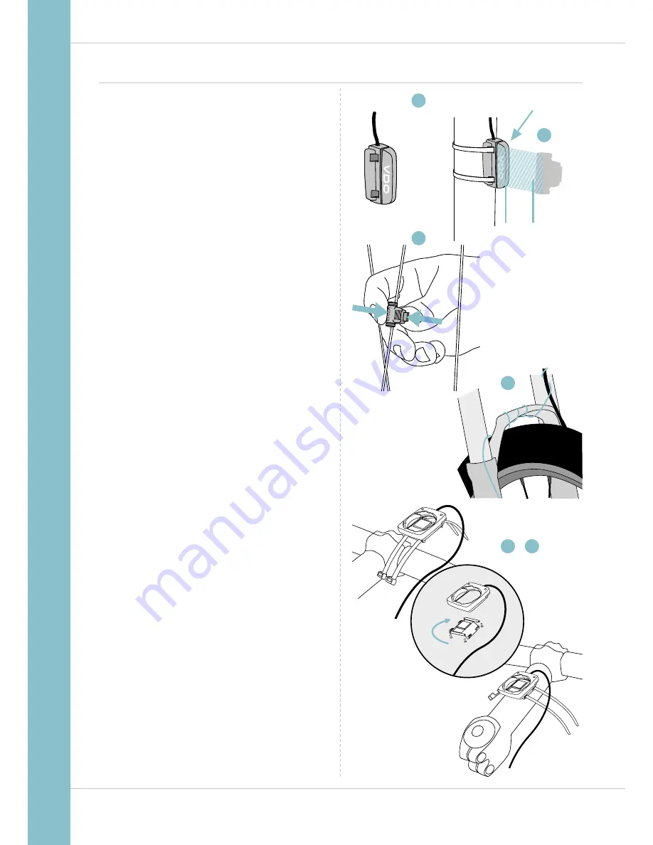
Attaching the bracket and the sensor
Start by attaching the sensor and the magnet.
STEP 1
Place the rubber shim under the sensor. Attach the sensor to
the fork side that corresponds to the side on which you later
want to attach the computer to the handlebars (right or left)
using the cable ties supplied (loosely at first, do not pull tight
just yet).
ATTENTION:
the sensor mark on the sensor should point to
the spokes. Depending on the space available, the sensor can
be fitted to the front, inside or back of the fork.
STEP 2
Attach the spoke magnet to an outside spoke. The rod-shaped
magnet core points toward the sensor with the VDO logo.
Align the magnet with the sensor marking on the sensor
at a distance of approx. 1- 5 mm.
STEP 3
Align the sensor and the magnet in their final positions and
fasten them in place: pull the cable ties tight and push the
magnet in firmly.
STEP 4
Move the cable along the fork until it reaches the fork bridge.
From there, wind the cable further along the brake line until it
reaches the handlebars.
STEP 5
Decide whether you want to use handlebar or stem attach-
ment and rotate the base of the handlebar bracket by 90°
accordingly. To do so, undo the screws on the bracket,
remove the foot and rotate it 90° then insert and tighten
the screws again.
ATTENTION:
do not overtighten the screws.
STEP 6
Guide the cable ties through the slot in the handlebar bracket,
place around the handlebars or the stem and pull (do not pull
tight just yet).
STEP 7
For handlebar attachment: align the computer angle
to achieve optimum readability.
Now pull the cable ties tight.
Use clippers to snip off protruding cable ends.
A helpful attachment video can be found on our website.
www.vdocyclecomputing.com/service
SENSOR


