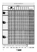
VARMEC VAR Series Скачать руководство пользователя страница 29

29

CONDIZIONI DI FORNITURA

I variatori Varmec vengono forniti come segue:

Già predisposti per essere installati nella posizione di montag-

gio come definito in fase di ordine

Collaudati secondo specifiche interne

Le superfici di accoppiamento non sono verniciate.

Sprovvisti di dadi e bulloni per il montaggio motori per la ver-

sione IEC.

Appositamente imballati per la spedizione

Please read this chapter carefully and follow all instructions be

-

fore installing the speed variator:

• 

Check that nothing has been damaged during transport or 

storage

• 

Make sure that the variator is free from all packaging and 

any eventual protective products

• 

Check that the information printed on the identification plate 

correspond to those specified on the order

• 

After making sure that the machine on which the variator is 

to be installed is completely switched off and cannot be ac

-

cidentally turned on, check that it is sturdy and rigid enough 

to withstand the weight and the forces generated by the vari

-

ator when running

• 

Make sure that the variator is correctly secured to avoid 

any kind of vibrations and that the coupling parts are flat 

and clean. Before assembling lubricate the contact parts to 

avoid seizures or oxidisation

• 

Check that the alignment between the speed variator and 

the operational machine is perfect

• 

Parts that connect to the variator’s output shaft must be 

machined to ISO H7 tolerance to avoid any tightly blocked 

couplings that could damage the variator. For the assem-

bly and removal of these parts use suitable pullers or ex

-

tractors  using  the  specifically  designed  threaded  hole  at 

the end of the output shaft. Do not use hammers or other 

improper tools that may damage the shafts or the support

-

ing stand

• 

Coupling the variator’s input hollow shaft is normally done 

with ISO h6 tolerance shaft. In all cases assembly must 

never be forced

• 

Make sure that the assembly of any pinions or jump pulleys 

on the shafts conforms to the admissibility checks of the 

resulting loads

• 

Check  that  the  voltage  printed  on  the  information  plate 

coincides with the main power supply

• 

Varnishing should not in any way touch worked parts: the 

edges of oil seals, existent holes on the breather plug and 

also the identification plate

• 

If shocks or overloads are expected  when running then 

safety motors, clutches and coupling limitators must be in

-

stalled

• 

If variators are installed externally there must be suitable 

protection against the exposal to atmospheric agents and 

solar  radiation.  If  installed  in  humid  areas  use  adequate 

protection on the reducer’s worked surfaces.

• 

It is advisable to use motors with 2 poles for intermittent 

running due to the elevated temperature that can be regi

-

stered during running times

• 

In the case of ambient temperatures not within -15°C and 

+ 50°C please contact our technical service department.

SUPPLIED TERMS

All Varmec variators are supplied as follows:

Ready made to be installed in the assembly position previously 

stated during ordering

Tested to our internal specifications

Coupling surfaces are not varnished

Nuts and bolts are not supplied for the assembly of motors for 

IEC versions

Appropriately and adequately packaged for transport

Per l’installazione del variatore è consigliabile attenersi alle se-

guenti indicazioni:

• 

Verificare che non vi siano stati danni durante lo stoccag-

gio o il trasporto

• 

Pulire accuratamente il variatore dai resuidi dell’imballag-

gio a da eventuali prodotti protettivi       

• 

Verificare che i dati riportati nella targhetta di identificazio-

ne corrispondano a quelli specificati in fase di ordinativo

• 

Verificare che la struttura della macchina sulla quale si in-

stalla il variatore abbia caratteristiche di rigidezza e di ro-

bustezza sufficienti a supportarne il peso proprio e le forze 

generate nel funzionamento; accertarsi che la macchina 

sia spenta e che ne sia impedito il riavvio accidentale

• 

II fissaggio sulla macchina deve essere stabile per evitare 

qualsiasi  vibrazione;  verificare  che  le  superfici  di  accop-

piamento siano piane e ben pulite. Prima del montaggio 

lubrificare le superfici di contatto onde evitare grippaggi o 

ossidazioni

• 

Assicurare l’allineamento tra variatore e macchina  ope-

ratrice

• 

Gli organi che vanno calettati sugli alberi di uscita del va-

riatore devono essere lavorati con tolleranza ISO H7 per 

evitare accoppiamenti troppo bloccati che potrebbero dan-

neggiare il variatore stesso. Per il montaggio e lo smon-

taggio di tali organi si consiglia l’utilizzo di adeguati tiranti 

ed  estrattori  usufruendo  dell’apposito  foro  filettato  posto 

in testa alle estremità degli alberi d’uscita. Non servirsi di 

martelli o altri strumenti impropri per non danneggiare gli 

alberi o i supporti dei variatori

• 

L’accoppiamento dell’albero di entrata cavo del variatore, 

viene normalmente eseguito con perni aventi tolleranze 

ISO h6; in ogni caso il montaggio deve avvenire senza 

forzature

• 

Accertarsi che il montaggio di pignoni o pulegge  a sbalzo 

sugli alberi dei variatori, sia conforme alle verifiche di am-

missibilità dei carichi risultanti

• 

Verificare  che  il  valore  della  tensione  di  alimentazione 

stampigliata sulla targhetta del motore elettrico coincida 

con la tensione di rete 

• 

La verniciatura non deve assolutamente interessare i piani 

lavorati, il bordo esterno degli anelli di tenuta, fori esistenti 

sui tappi di sfiato e la targhetta di identificazione

• 

Se il funzionamento prevede urti o sovraccarichi, si devo-

no adottare salvamotori, limitatori di coppia, giunti di sicu-

rezza, ecc.

• 

Per i variatori installati all’esterno prevedere opportune 

protezioni contro l’esposizione diretta agli agenti atmosfe-

rici e alla radiazione solare. Per installazioni in ambienti 

umidi, adottare adeguati protettivi sulle superfici lavorate 

del riduttore  

• 

L’utilizzo dei motori a 2 poli è consigliato per servizi inter-

mittenti, a causa dell’elevata temperatura che si può regi-

strare durante il funzionamento

• 

Nel caso di temperature ambiente non comprese tra -15°C 

e +50°C contattare il nostro servizio tecnico.
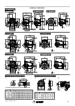
INSTALLAZIONE

INSTALLATION

Содержание VAR Series

Страница 1: ...1 Variatori di velocit Speed variators VAR...

Страница 2: ...CARICHI RADIALI E ASSIALI 10 RADIAL AND AXIAL LOADS 10 VERIFICHE 10 CHECK POINTS 10 LUBRIFICAZIONE VARIARIDUTTORI 11 LUBRICATION VARIATORS WITH REDUCTION STAGES 11 SELEZIONE MOTOVARIATORI 13 MOTOR SP...

Страница 3: ...tore Speed reducer limited output torque M2MIN Nm Momento torcente minimo richiesto in uscita variatore Minimum required torque at speed reducer output MC2 Nm Momento torcente di calcolo in uscita var...

Страница 4: ...za per mezzo di interruttori di prossimit induttivi Potenze applicabili da 0 12 a 4 0 kW Coppia in uscita da 0 46 Nm a 316 Nm Variazione giri i 1 5 DESCRIPTION VARIABLE SPEED DRIVES VARMEC Variators a...

Страница 5: ...stati progettati interamente con l ausi lio di programmi tecnici su computer Le casse e le flange in ghisa ad alta resistenza verniciate ven gono lavorate su moderni centri di lavoro a controllo nume...

Страница 6: ...AMETER OUTPUT SHAFT 11 32 DIAMETRO FLANGIA USCITA DIAMETER OUTPUT FLANGE 120 250 350 NUMERO DI GIRI MINIMO IN USCITA rpm MINIMUM SPEED IN OUTPUT rpm NUMERO DI GIRI MASSIMO IN USCITA rpm MAXIMUM SPEED...

Страница 7: ...EQUENCY CLASSE ISOLAMENTO INSULATION CLASS POSIZIONE MORSETTIERA POSITION OF TERMINAL BOX OPZIONI OPTIONS T 80A 4 230 400 50 CLF IP55 A PROTEZIONE PROTECTION T trifase TF trifase autofrenante M monofa...

Страница 8: ...relazione dove Ju Kgm2 momento d inerzia dinamico delle masse esterne Jm Kgm2 momento d inerzia del motore elettrico Numero avviamenti ora Number of starts and stops hour h d Tab 1 The service factor...

Страница 9: ...he performance table I valori indicati nelle tabelle di selezione sono determinati tenendo in considerazione il fatto che la coppia erogata dal solo variatore sia limitata dal valore massimo trasmissi...

Страница 10: ...ichi radiali massimi Fr2 sopportabili dal variatore pertanto dovr essere rispettata la seguente condizione I carichi indicati sono riferiti alla mezzeria della sporgenza dell al bero lento e valgono p...

Страница 11: ...OIL OLIO SINTETICO SYNTHETIC OIL 460 320 220 460 320 220 150 Temperatura ambiente Amb Temp Tc C 5 a 45 0 a 40 5 a 100 15 a 100 15 a 90 25 a 80 30 a 70 FORNITORE MANUFACTURER MINERALE MINERAL MINERALE...

Страница 12: ...a small quantity of grease contained in the sealed chamber between the two bearings of the output shaft which must be replenished only in the case of removal of the cam flange according to the instruc...

Страница 13: ...0 131 40 32 48 VAR022 10 50 018 4 63B4 13 17 65 113 11 113 11 25 26 VAR052 20 100 018 6 71A6 15 75 109 22 20 91 VAR022 7 5 37 5 018 2 63A2 20 100 84 80 16 24 VAR022 10 50 018 2 63A2 20 100 84 87 16 25...

Страница 14: ...n1 900 min 1 7 32 5 156 50 94 55 VAR102 10 50 037 6 80A6 8 38 131 4 85 98 VAR052 7 5 37 5 037 4 71B4 10 50 131 40 66 76 VAR052 10 50 037 4 71B4 10 50 156 50 59 10 VAR102 16 80 037 6 80A6 13 65 152 00...

Страница 15: ...B4 n1 1400 min 1 90S6 n1 900 min 1 10 50 156 50 123 21 VAR102 10 50 075 4 80B4 10 25 50 309 25 309 25 131 81 VAR202 16 80 075 6 90S6 16 80 156 50 77 00 VAR102 16 80 075 4 80B4 20 60 100 132 76 132 76...

Страница 16: ...800 min 1 90S4 n1 1400 min 1 90L6 n1 900 min 1 10 37 50 309 25 309 25 193 32 VAR202 16 80 110 6 90L6 16 43 80 270 86 270 86 124 28 VAR202 16 80 110 4 90S4 20 100 156 50 90 36 VAR102 10 50 110 2 80B2 2...

Страница 17: ...0LA4 80 278 400 84 00 84 00 47 47 VAR201 40 200 220 2 90L2 125 407 625 57 33 57 33 30 31 VAR301 125 625 220 4 100LA4 150 502 750 46 50 46 50 26 26 VAR201 75 375 220 2 90L2 220 589 1100 32 41 32 41 18...

Страница 18: ...0 1000 8 60 1 65 753 VAR021 100 500 018 2 0 25 2800 2 200 1000 11 94 2 29 753 VAR021 100 500 025 2 VAR 2 2 0 12 900 6 5 25 131 4 43 45 2685 VAR022 7 5 37 5 012 6 0 12 1400 4 7 5 37 5 131 40 31 37 2248...

Страница 19: ...ANGE VAR TIPO TYPE L M N h8 O P Q 2 0 2 1 2 2 B5 B3 B5 120 100 80 7 2 5 10 140 115 95 9 3 10 160 130 110 11 3 10 200 165 130 11 3 10 SX DX SX DX SX DX SX DX SX DX SX DX 1 2 3 1 2 3 1 2 3 1 2 3 140 112...

Страница 20: ...0 07 20 07 4 57 909 VAR051 100 500 025 4 0 37 1400 4 100 195 500 20 07 20 07 6 77 780 VAR051 100 500 037 4 0 37 2800 2 200 240 1000 16 30 16 30 3 38 753 VAR051 100 500 037 2 0 55 2800 2 200 358 1000 1...

Страница 21: ...ANGE VAR TIPO TYPE L M N h8 O P Q 5 0 5 1 5 2 B5 B3 B5 120 100 80 7 2 5 10 140 115 95 9 3 10 160 130 110 11 3 10 200 165 130 11 3 10 1 2 3 N L M O P Q SX DX SX DX 1 2 3 160 112 191 76 M6x12 75 110 140...

Страница 22: ...0 216 500 27 00 27 00 9 60 1080 VAR101 100 500 055 4 0 75 1400 4 100 295 500 27 00 27 00 13 06 963 VAR101 100 500 075 4 0 75 2800 2 200 363 1000 21 90 21 90 6 53 924 VAR101 100 500 075 2 1 10 2800 2 2...

Страница 23: ...TIPO TYPE L M N h8 O P Q 10 0 10 1 10 2 B5 B3 B5 160 130 110 11 3 5 11 200 165 130 11 3 5 11 SX DX SX DX SX DX 1 2 1 2 1 2 3 SX DX N L M O P Q SX DX SX DX 1 2 3 200 149 241 89 5 M8x16 85 140 170 18 1...

Страница 24: ...900 6 70 174 350 45 56 45 56 19 42 1840 VAR201 110 550 075 6 1 10 900 6 70 256 350 45 56 45 56 28 48 1585 VAR201 110 550 110 6 1 10 1400 4 110 292 550 39 90 39 90 18 31 1540 VAR201 110 550 110 4 1 50...

Страница 25: ...FLANGE SX DX SX DX SX DX SX DX 1 2 3 1 2 1 2 1 2 3 SX DX N L M O P Q VAR TIPO TYPE L M N h8 O P Q 20 0 20 1 B5 B3 B5 160 130 110 11 3 5 11 200 165 130 13 3 5 11 250 215 180 14 4 13 20 2 B3 B5 200 165...

Страница 26: ...0 400 2 1 50 900 6 45 139 225 113 80 113 80 55 90 2442 VAR301 70 350 150 6 2 20 1400 4 70 234 350 99 70 99 70 52 71 2025 VAR301 70 350 220 4 3 00 1400 4 70 319 350 99 70 99 70 71 87 1785 VAR301 70 350...

Страница 27: ...28 60 M8 18 31 8 50 5 5 VAR TIPO TYPE L M N h8 O P Q 30 0 B5 B3 B5 250 215 180 14 4 14 30 1 200 165 130 13 3 5 11 250 215 180 14 4 14 SX DX 1 2 3 SX DX 2 VAR 30 1 B3 B5 250 182 295 94 212 258 330 55 2...

Страница 28: ...dal no stro sito internet oppure interpellateci In conformit alla Direttiva Atex 2014 34 UE le serie di variatori VARMEC ATEX sono marcate II 3D EEx c T135 C ATEX Varmec variators can be supplied for...

Страница 29: ...installed in the assembly position previously stated during ordering Tested to our internal specifications Coupling surfaces are not varnished Nuts and bolts are not supplied for the assembly of moto...

Страница 30: ...nuazione o la scomparsa della rumorosit Qualora ci non avvenga sar necessario sostituire l anello di frizione prima di effettuare questo intervento consigliabile consultare il nostro Servizio Tecnico...

Страница 31: ...protette con prodotti antiossidanti Per periodi di stoccaggio superiori ai 6 mesi i variatori dovran no avere le parti lavorate esterne e quelle di accoppiamento ricoperte di grasso per evitare ossida...

Страница 32: ...5 12 3 1 1 12 4 0 75 12 90S 24 50 8 305 148 181 200 130 165 3 11 5 11 140 95 115 3 M8 1 85 12 8 2 2 15 1 5 14 5 1 1 14 3 90L 330 1 85 16 5 3 19 7 2 2 18 5 1 5 19 100 28 60 8 370 156 198 250 180 215 2...

Страница 33: ...4 5 1 1 14 5 0 75 14 90S 24 50 8 357 148 181 200 130 165 3 11 5 11 140 95 115 3 M8 1 85 15 2 2 17 3 1 5 16 9 1 1 16 7 90L 382 1 85 18 5 3 23 2 2 21 5 1 5 22 5 100 28 60 8 442 156 198 250 180 215 2 5 1...

Страница 34: ...34...

Страница 35: ...35...

Страница 36: ...year the invoi cing date VARMEC will replace or repair defective parts but will not accept any further charges for direct or indirect damages of any kind The warranty will become null and void if the...

Отзывы: