1101
Illustrations may differ from actual product
Subject to printing/proofreading errors
1 8
Operation and maintenance
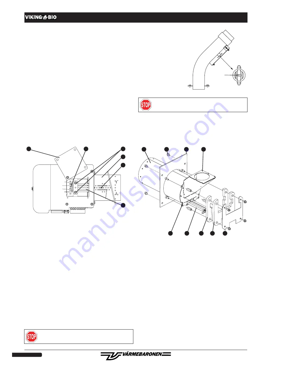
Changing ignition element
BLUE
BLACK
BLUE
BLACK
a
f
e
c
b
d
a. Cover
d. Nut and tab washer for ignition element
b. Electrical connections
e. Ignition element
c. Allen screws
f. Inner burner pipe
A. Detach the burner from the boiler. Remove the burner's cover, open
the quick attachments and release the burner pipe and flange from the
burner.
B. Turn the burner upside down so that the lower side is accessible.
Unscrew the screws holding the cover 'a'.
C. Detach the cables on the electrical connections 'b'.
D. Unscrew the screws 'c' and nut 'd'. Press the screw on which the nut
was located into the burner pipe.
E. Pull the ignition element out through the hole.
F. Refit in reverse order with a new ignition element. Do not tighten nut 'd'
too hard, max. 0.5 Nm.
Pay attention to how the ignition element should be connected e
lectri-
cally. See the wiring diagram.
Reset button
Changing inner burner pipe
a
b
c
d
e
f
g
h
i
a. Inner burner pipe
e. Ignition element
b. Flange
f. Gasket, inner, 2, right/left.
c. Screw
g. Gasket, outer
d. Shaft with end wall
h. Panel
i. Lug
A. Detach the burner from the outer burner pipe.
B. Unscrew the four screws 'c' on the flange against the burner housing.
Pull out all parts from the burner housing, as shown in the above figure.
C. Separate as shown in the figure.
Notice how gaskets 'f' and 'g' are fitted.
The inner burner pipe is fixed to the end wall with the lug 'i'. Turn the
lug so that the inner burner pipe can be detached.
D. Refit. See 'Changing ignition element' for how the cables should be
attached to the ignition element.
Check the condition of the outer burner pipe as well.
Switch off the power to the burner before the work begins.
Resetting the thermal relay
When the thermal relay on the
downpipe has been triggered,
the 'ALARM' indicator lights up
constantly.
When it is reset, the burner must
be dead.
Remove the thermal relay's
enclosure on the downpipe.
Reset it by pressing the button
on the thermal relay.
Refit the enclosure and restart
the burner.
Switch off the power to the burner before the thermal relay's
enclosure is removed.
Safety system
The p ellet system's safety system consists of:
• overheating protection against excessive boiler temperature.
• thermal relay in downpipe.
• non-combustible hose (melts) between feed auger and downpipe.
• fan with fan guard.
• photoresistor for flame monitoring.
• blockage if the ambient temperature is too high.
The majority of the functions cannot be influenced by the user and require
no special control.
Check regularly that the hose between the feed auger and the downpipe
is intact.


