background image

OPERATING MANUAL - 

SAXMAG V 

Page 18 


Temperature monitoring


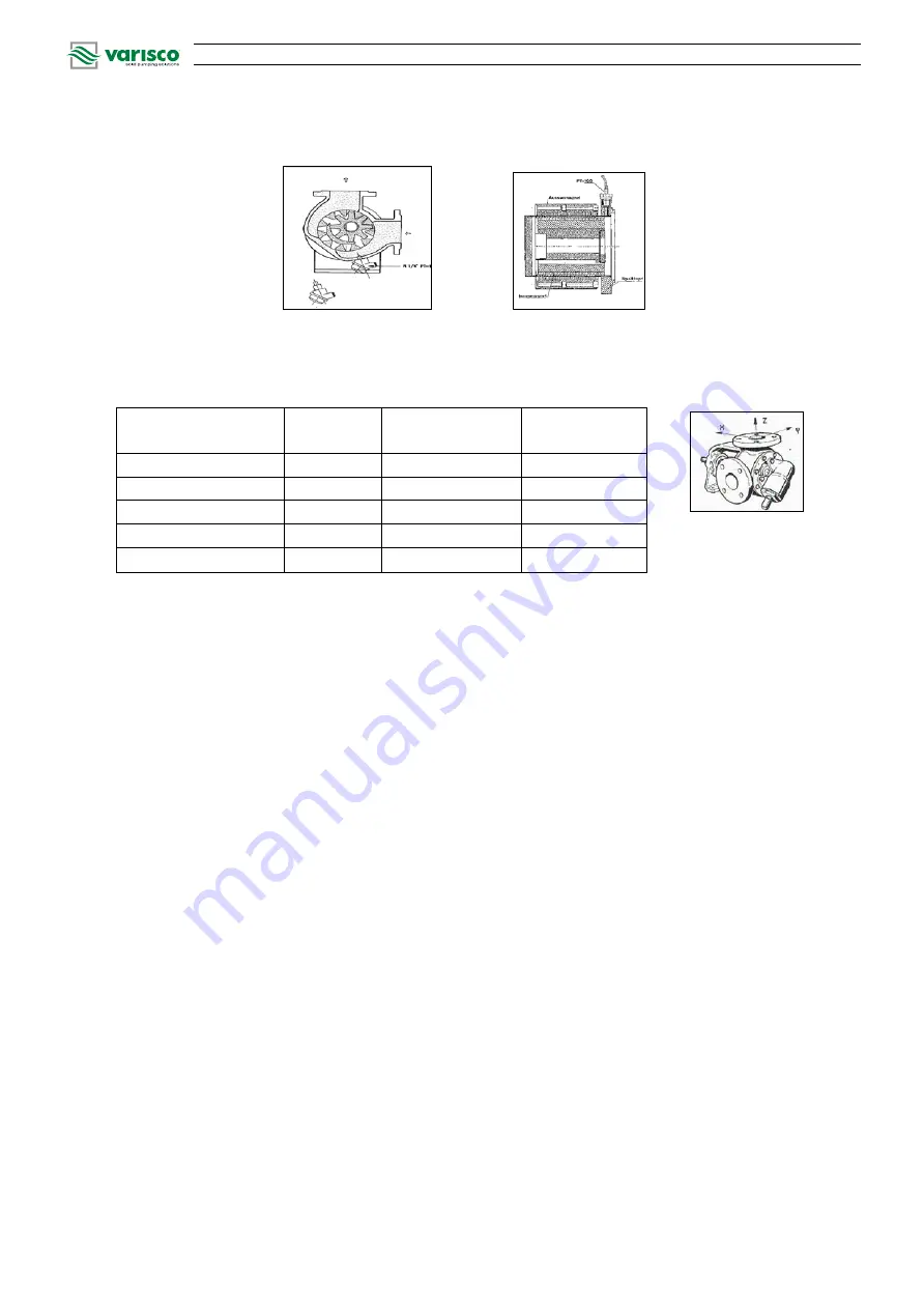
4.3.5  Permissible forces, torques and moments on the pump branches


Pump Type


Flange


(DN)


F

x

, F

y

, F

z


N


M

x

, M

y

, M

z


Nm


V6, V12


15


196


99


V20, V25-2, V30-2


40


520


260


V60-2


50


650


330


V80-2


80


1,040


520


V100-2


100


1,300


660


4.3.6  Expected noise 


The sound pressure level of V-Series Varisco pumps with drive, as measured at the pump height at 1 m 
distance from the pump, is less than 75 dB for all models. 


4.4 

Accessories


Shaft coupling:   flexible coupling with / without adapter sleeve 
Touch guard:  

coupling guard 

Baseplate:  

welded fabrication, for complete (to ISO 3661) unit (pump and motor) of torsionally 
rigid design. 


Where complete units are delivered the coupling and the coupling guard will be 
furnished by the supplier. 


4.5 

Dimensions and weights


Dimensions and weights can be seen from the pump's installation drawing. 


Mounting/Installation


5.1 

Safety regulations


Equipment operated in  potentially  explosive atmospheres must comply with relevant explosion 
protection regulations. This requirement is clear from the rating plates of the pump and the motor. 
Persons who have a pacemaker should not be allowed in the vicinity of the strong magnetic  field 
generated by the magnetic coupling. Persons within 2 m of the pump would be risking their lives! 


Содержание SaxMag V Series

Страница 1: ...V Series Internal Gear Pumps with Magnetic Coupling Operating Manual Ed 2013 03 Rev 00 Code 555...

Страница 2: ...27 1 1997 Explosive atmospheres Explosion Protection Part 1 Basic concepts and methodology EN13463 1 2001 Non electrical equipment for potentially explosive atmospheres Part 1 Basic method and require...

Страница 3: ...spare parts by customer 8 2 8 Improper modes of operation 8 2 9 Explosion protection 8 2 9 1 Filling the unit 9 2 9 2 Special operating conditions 9 2 9 3 Markings 9 2 9 4 Checking the sense of rotati...

Страница 4: ...4 4 Accessories 18 4 5 Dimensions and weights 18 5 Mounting Installation 18 5 1 Safety regulations 18 5 2 Installation 19 5 2 1 Checks 19 5 2 2 ATEX Certification 19 5 3 Checks prior to installation 1...

Страница 5: ...mentation If you have any questions or require further information please do not hesitate to consult the manufacturer Pump series size major operating data and the series number are indicated on the r...

Страница 6: ...may cause hazards to persons Warning of electric power Safety symbol according to IEC 417 5036 and explosion protection Safety instructions pertaining to machines and their functions are indicated by...

Страница 7: ...ions may result in the loss of any and all claims for damages In particular non compliance of safety information may result in the following hazards risks Failure of important machine equipment functi...

Страница 8: ...hen the machine stands still It is imperative to follow the shutdown procedure described in this Operating Manual Pumps or pump units that discharge media hazardous to health must be decontaminated Al...

Страница 9: ...rmal energy generated in the containment shell or on the external magnet may also cause an inadmissible rise in temperature If such risk exists make sure to take suitable monitoring measures see 4 3 4...

Страница 10: ...n the piping The pump must not discharge against a closed system 2 9 6 Temperature limits Under normal operating conditions expect the highest temperatures to occur at the surface of the pump casing t...

Страница 11: ...f the antifriction bearings depends on the mode of operation and the specific conditions on site Regular checks of the running noise prevent the risk of excessive temperatures caused by overheated bea...

Страница 12: ...ng devices for transport The transport locking devices supplied with the pump can be removed after transport During start up and maintenance ensure safe transport of all components To this end suitabl...

Страница 13: ...the filled in liquid might contaminate the product to be pumped Never start up the pump with water and do not leave any traces of water in the pump 3 3 Return Pumps that have delivered corrosive or po...

Страница 14: ...to the internal magnet core that is mounted to the pump shaft The magnetic field generated by the motor driven magnet hub with the externally placed set of permanent magnets causes the internal magne...

Страница 15: ...rough the pump the point where the teeth come out of mesh governs the phase of the liquid entering between the rotors and is therefore physically located close to the suction zone The liquid is carrie...

Страница 16: ...of this Operating Manual 4 3 Main components 4 3 1 Magnetic coupling The external rotor is driven by an electric motor through antifriction bearings It is due to the magnetic forces of the permanent...

Страница 17: ...bearing clearance and high temperature grease packing have sealing washers on either side The pump end shaft is supported in hydrodynamic carbide plain bearings which are lubricated by the pumped flui...

Страница 18: ...g guard Baseplate welded fabrication for complete to ISO 3661 unit pump and motor of torsionally rigid design Where complete units are delivered the coupling and the coupling guard will be furnished b...

Страница 19: ...se as possible to the tank of the liquid to be pumped and allow sufficient space around to facilitate maintenance work inspection and checks Keep enough free space specifically in front of the pump to...

Страница 20: ...g system 5 5 Piping Piping connected to the pump must not transmit forces torques or moments to the latter it may be necessary to support connected pipes upstream of the pump Piping must be adequately...

Страница 21: ...ssible loads in the technical section Where the liquid can reach high temperatures it must be ensured that expansion joints are installed in the piping Check the motor s electrical connections the bal...

Страница 22: ...pumped medium or discharge side clogging Overtemperature resulting from recirculation when the pressure relief valve has operated Operator s failure to conduct checks as necessary Referring to the app...

Страница 23: ...a dangerous electrostatic charges which can result in discharge sparks that could ignite a potentially explosive atmosphere are ruled out as trouble to be expected since the thickness of a paint coat...

Страница 24: ...tly set or leaking 8 Insufficient suction pressure 9 Worn pump components gears sliding plate 1 Reduce pressure drop 2 Inspect suction line for leaks 3 Check speed contact manufacturer 4 Eliminate lin...

Страница 25: ...act the manufacturer High containment shell temperature Excessive viscosity Product flow for cooling interrupted Contact the manufacturer Check filter and design High casing temperature Foreign matter...

Страница 26: ...sed as a result of non observance of this manual The specific safety requirements in relation to strong magnetic fields must be strictly observed Persons who have a pacemaker should not be allowed to...

Страница 27: ...ed If damaged replace it This also applies to all other pump seals Pull off the pinion 03 with pressed in plain bearing 37 from the cover 04 via the pin 06 Heat the pinion 03 to approx 80 C When the t...

Страница 28: ...OPERATING MANUAL SAXMAG V Page 28 9 3 Disassembly of the pump casing 01 Unscrew the screws 44 and pull off the casing 01...

Страница 29: ...ring bracket M1 01 On principle the plug in unit should only be separated from the external magnet M2 02 by radial guidance restricted guidance Make sure that the external magnet M2 02 and the contain...

Страница 30: ...r M3 12 from the pump shaft M3 08 Separate the internal magnet M2 04 from the pump shaft M3 08 with the help of a suitable pull off device Remove the thrust washer M3 11 from the pump shaft M3 08 Pull...

Страница 31: ...th magnet hub M2 01 from the bearing bracket M1 01 in the direction of the external magnet M2 02 Unscrew the bolts M1 08 and dismantle the ball bearing cover M1 02 from the bearing bracket M1 01 Remov...

Страница 32: ...ase see the table below for further information Class Pump type V25 2 V30 2 V50 3 V60 2 V70 2 V80 2 V85 2 V100 2 1 0 2 mm 0 2 mm 0 3 mm 0 5 mm 2 0 3 mm 0 5 mm 0 7 mm 0 7 mm 3 0 5 mm 0 7 mm 1 0 mm Pump...

Страница 33: ...ontact with liquids subject to labelling requirements under the law on hazardous substances and or dangerous goods If known please state the last medium pumped Prior to shipment provision the pump has...

Страница 34: ...Page 34...

Страница 35: ...Page 35...

Страница 36: ...rd 35129 PADOVA Italy Tel 049 82 94 111 Fax 049 82 94 373 www variscospa com Vendite Italia Tel 049 82 94 111 Fax 049 82 94 373 italia variscospa com International sales Ph 39 049 82 94 111 Fax 39 049...

Отзывы: