4
T
able
o
f
c
onTenTs
i
nsTallaTion
and
fixing
:
The ambient temperature around the machine must not exceed 113
o
F.
If the mixer is placed on a table, it must
always
be bolted into the table top. The bolts fixing the mixer on the pallet can be used
for this, no nuts are needed as there are threads in the bottom plate of the mixer
(see page 5)
.
Electrical connection:
For the benefit of service staff, it should be clear to see when the mains plug to the mixer has been removed from the socket in
the wall.
Ensure that the voltage, phase and hertz printed on the identification plate of the mixer are the same as that at the place of
installation. The identification plate is located at the top of the right side of the mixer. Be sure the mixer is properly connected
to the incoming power supply and the ground or earth connection is made. The arrow on the front of the planetary head (see
drawing 2, page 1), indicates the direction of rotation of the planetary head. On three-phase motors the direction of rotation can
be changed by interchanging two phases of the connecting cable or the motor. Electrical connections must be made in accord-
ance with local regulations.
c
ommissioning
:
Bowl, tools and safety guard should be cleaned before use – see section on
Cleaning, page 6.
r
ecommended
Use
of
The
machine
:
The machine is designed for the manufacture of products that do not trigger any reactions or release substances that may be
harmful to the user when in use.
The machine must not be used in an explosive atmosphere.
The mixer is designed for commercial use in kitchens, catering outlets and bakeries.
The machine may only be used as specified in this manual.
Unless the change is recommended by the manufacturer, modifying the machine is prohibited.
If the machine is fitted with an attachment drive, only accessories produced or recommended by Varimixer should be attached.
U
npacking
: ........................................................................................................................................................2
T
ransporT
: .......................................................................................................................................................2
i
nsTallaTion
and
fixing
: ...................................................................................................................................4
c
ommissioning
: .................................................................................................................................................4
r
ecommended
Use
of
The
machine
: ...................................................................................................................4
c
onsTrUcTion
of
The
mixer
: .............................................................................................................................5
T
echnical
daTa
: ................................................................................................................................................5
T
he
maximUm
capaciTy
of
The
mixer
: .................................................................................................................5
d
imension
skeTch
: ............................................................................................................................................5
s
afeTy
: .............................................................................................................................................................6
c
orrecT
Use
of
Tools
: .....................................................................................................................................6
a
TTachmenT
h
Ub
: ..............................................................................................................................................6
r
ecommended
max
.
speeds
...............................................................................................................................6
o
peraTing
i
nsTrUcTions
....................................................................................................................................7
o
verloading
: ....................................................................................................................................................8
c
leaning
: ..........................................................................................................................................................8
l
UbricaTion
and
grease
Types
: ........................................................................................................................8
s
ervice
i
nsTrUcTions
........................................................................................................................................9
m
achine
c
olUmn
............................................................................................................................................14
l
ifTing
s
ysTem
................................................................................................................................................16
p
Ulley
s
ysTem
................................................................................................................................................18
p
laneTary
h
ead
.............................................................................................................................................20
a
TTachmenT
h
Ub
.............................................................................................................................................22
e
lecTrical
c
omponenTs
.................................................................................................................................24
b
owl
s
creen
.................................................................................................................................................26
T
ools
and
a
TTachmenTs
................................................................................................................................28
e
lecTrical
d
iagram
.......................................................................................................................................30
Содержание V20
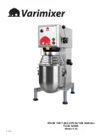
Страница 1: ...1 SPARE PART AND OPERATION MANUAL FOOD MIXER Model V20 012016...
Страница 9: ...9 Service Instructions 5 55 3 21 4 40 41 9 7 22 1 10 6 8 42 43 2 16 17 18 20 19 44...
Страница 14: ...14 Machine Column 20 18 19 11 13 10 17 9 12 6 15 3 7 14 5 16 2 1 4 8 06020 0407 10A...
Страница 16: ...16 Lifting System 56RN20 15 20N 62Z 20N 65 1M 20N 68 5M 22 23 24 21 21A...
Страница 22: ...22 Attachment Hub RN20 10 6M9 12 Hub 17 11 16 3 15 12 14 13 7 1 6 4 5 2 8 9 10 2 I D u 1 I D 18...
Страница 24: ...24 Electrical Components 1 19 4 5 13 12 11 3 2 6 7 10 9 8 16 17 18 15 14 15 20...
Страница 26: ...26 Bowl Screen 1 5 10 2 3 9 7 8 4 6 11 20 19 12 13 14 15 18 16 17 56SN20 15...
Страница 28: ...28 Tools and Attachments 1 2 10 10 10 10 3 4 5 6 11 7 8 9 12 13 14 15 16 17 10 19 20 18 21...
Страница 30: ...30 Electrical Diagram...
Страница 31: ...31...
Страница 32: ...32 14240 South Lakes Drive Charlotte NC 28273 800 222 1138 www varimixer com...


