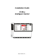
IC-68
ND
INSTALLATION GUIDE
3
The purpose of this guide is to fully inform the electrician on proper wiring and installation
procedures for the IC-68
ND
. Full conformity of the Installation and User’s Guide will lead to a
successful installation and proper functioning of the IC-68
ND
control .
1. Unpacking
Unpack the IC-68
ND
and inspect contents for damage. Should the contents appear to be
damaged, contact your local distributor to arrange for the return of the damaged material.
The package should contain the following standard item :
•
1 IC-68
ND
•
1 Temperature probe
•
1 Spare Power Fuse
•
1 Spare FAN 1 and FAN 2 fuse
•
1 Installation Guide
•
1 User’s Guide package including list of equipment, wiring diagrams, parameter list, and
detailed description of the configuration.
2. Mounting Hardware Required
This is the list of the mounting hardware needed which is not included with the product :
•
Shielded two-wire cable, AWG #18 (to extend probes)
•
Shielded two-wire low capacitance cable, AWG #18 to #22 (used for communication)
•
3 screws : 1 #8 X 1’’, 2 #6 X 1’’ (to hang the unit onto the wall)
•
Screwdrivers
•
Hammer (to punch out the knock outs)
•
Soldering iron kit or approved sealed connectors
The manufacturer recommends that the following installation instructions be followed as closely
as possible and all work be performed by a certified electrician. Failure to do so may void the
warranty.
www.monitrol.com


