


Hurricane MaX
to check the automatic blade brake function during its run-in.
2.5.4.1 A
DJUSTMENT
OF
THE
BELT
DRIVE
TENSIONER
PULLEYS
This simple test will determine the correct function of the tensioner pulleys.
a)
Travel function test:
The machine with its travel turned ON has to overcome the terrain unevenness of 10 cm high - curb is
suitable, for example.
b)
Working tool drive function test:
The belt starts driving (the working tool starts spinning) already at the 1/3 of the working
tool drive lever clutch step.
If at least one of the checks failed, it is necessary to adjust the tensioning pulleys!
If you are not sufficiently manually skilled, have the operations done by an authorized service centre.
2.5.4.1.1 T
RAVEL
FUNCTION
ADJUSTMENT
If you are not sufficiently manually skilled, have the operations done by an authorized service centre.
For electric starter brush cutters, we recommend that you cut the strap that holds the harness to the top gearbox cover.
Remove the rear upper plastic
gearbox cover
1
(in
Fig. 12
), so you can see both belts securing the machine’s forward travel.
Secure the cable harness
against its contact with the gear moving parts. It may be damaged or destroyed.
Try again to overcome the terrain inequality and visually check which belt is slipping.
(Marking
A
,
B
, and
C
in
Fig. 15
and
is common and always applies to the same bowden.)
1)
If the belt slips on the right side of the gearbox
(
Fig. 6
), tighten it by unscrewing the screw (
C
on
Fig. 17
) the bowden
end
in the arrow direction (away from the frame) by approximately 1 mm. Continue tensioning until the machine overcomes
some uneven terrain and simultaneously does not start moving forward when the travel clutch lever is released. If it is no longer
possible to unscrew the bolt (
C
), unscrew it fully against the direction of the arrow and hook the spring at the end of the cable
into the distal opening in the pulley arm. Then repeat the steps to tighten the belt.
2)
If the belt slips between the engine and gearbox
, tighten it with its tensioning pulley (
1
in
Fig. 19
). Release the
tensioning pulley by releasing the nut located on the engine plate using a suitable tool (such as a screwdriver) and tension the
pulley in the arrow direction. Once tensioned, tighten the nut, please. Then check the correct travel operation.
As soon as you cannot adjust the tensioning pulleys so that the belt does not slip, the belt must be
replaced.
Upon completion of the adjustment, be sure to attach the harness to the gearbox cover with a spare pull tape. Two
straps are left upon the machine assembly.
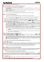
2.5.4.1.2 W
ORKING
TOOL
DRIVE
FUNCTION
ADJUSTMENT
:
Remove front
plastic cover
1
in
Fig. 10
>1
, so you can see the disk drive belt and pulley (
Fig. 15
). (
Marking
A
,
B
and
C
in
Fig. 15
and
s common and always applies to the same bowden.)
1)
Tighten the belt by unscrewing
bolt
A
in
Fig. 16
by approximately 1 mm in the arrow direction and check the working tool
drive clutch function. Continue tensioning until the belt drive starts spinning the working tool in about 1/3 of the lever step and at
the same time the belt drive is not carried away when the tool clutch lever is released. If it is no longer possible to unscrew bolt
A
, screw it in fully against the arrow direction and hook the spring at the end of the cable into the distal opening in the pulley
arm. Then repeat the steps to tighten the belt.
Always check the automatic brake function after any adjustment - Chapter 2.5.4.3 .
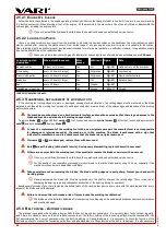
2.5.4.2 V-B
ELT
C
HANGE
Replace the V-belt
with a new one if the belt is so worn out by the operation that it is no longer possible to tension it with its tensioning
pulleys. The exact process of changing the individual belts is not provided here because it would exceed the scope of these operating
instructions. During the replacement, follow
Fig. 20
and
Fig. 6
Observe the belt path around all the guide elements
!
If you are not sufficiently manually skilled, have the operations done by an authorized service centre.
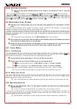
2.5.4.3 B
RAKE
FUNCTION
CHECK
AND
ADJUSTMENT
Check the automatic brake function after every 10 hours of operation. You may perform a continuous check during your work.
Each time
the working tool clutch lever is released, the automatic brake must stop the spinning working tool within 5 seconds.
Do not continue working until you clear the automatic brake fault.
If you are not sufficiently manually skilled, have the operations done by an authorized service centre.
If the brake does not stop the spinning working tool within the aforementioned time, it is necessary to adjust the bowden of brake
B
in
Fig. 15
. Screw in the adjusting bolt that secures the brake bowden cable (
B
in
Fig. 16
) to the machine frame against the
arrow direction (towards the frame) so that the axle clearance of the cable in the adjusting bolt is 1 mm. Check the automatic brake
85
Only for
F-580BiS
.
86
You may also utilise bolt
C
in
Fig. 18
on the opposite end of the bowden attached to the handlebar crossbar. In this case, screw it in away from the handlebar crossbar, in the
arrow direction.
87
You may also utilise bolt
A
in
Fig. 18
on the opposite bowden end attached to the handlebar crossbar. In this case, screw it away from the handlebars.
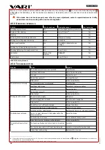
88
Use exclusively original spare parts.
If you use belts from other manufacturers, proper operation of the drive cannot be guaranteed.
33
Re
vi
ze
1
0/
20
19
Содержание Hurricane MaX F-580
Страница 2: ......
Страница 4: ...Z ru n list CZ...
Страница 21: ...Hurricane MaX 21 Revize 10 2019...
Страница 55: ...Hurricane MaX 55 Revize 10 2019...
Страница 61: ......
Страница 62: ......
Страница 63: ......


