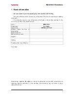
Vari BDR-595 E EuroAdela Скачать руководство пользователя страница 10


BDR-595 E EuroAdela


10 


6 Instructions for use 

6.1 Machine assembly 

 
Ask your dealer to provide machine unpackaging and briefing. 
 
Grip points for unpackaging the machine from the box: Front – Mowing disk; Rear – the  

„U“ tube of the machine frame. 

 
Should you do the machine assembly yourself, please follow the below instructions: 

Note: Washer size (e.g. Ø6.4mm) is always presented as the diameter of washer hole. 
 
1. Take the machine out from the box and all parts from the packages. 
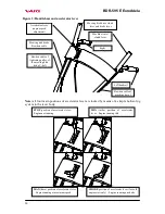
2. Slip the front part of screen frame (1a) into the rear part of screen frame (1b) and connect 

them by means of M6x16 bolts (2) with small flat washers Ø6.4mm (3). 

3. Put the assembled screen frame on a flat surface (table, floot, etc.) and slip the screen (4) 

onto the longitudinal beam on the front part of screen frame with its back side out. Bolt 
the  screen  (4)  to  the  assembled  apron  frame  by  means  of  two  bolts  M6x16  (2)  with 
washers Ø6.6mm (5) and self-locking nuts M6 (6) with small flat washers Ø6.4mm (3). 
Provide the bolt heads with plastic caps (7). Then sling the screen sides over the screen 
frame so that they are in the position illustrated in Fig. 2a. 

4. Turn the handlebars (8)so that the handrails point to the rear of the machine. Attach the 

handlebars (8) onto the frame tubes at a required height by means of bolts with squares 
(9), small flat washers Ø8.4mm (10) and plastic rosebits with internal tread (11). Fix the 
Bowdens to the tubes of handlebars by means of two plastic tightening tapes. 
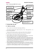
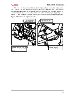
Driving wheels 

Engine 

Handleba

rs 

Mowing disk drive gear 

lever with brake 

Accelerator lever (adjustment 

of engine speed) 

Machine travel gear 

clutch lever 

Plastic rosebit to 

adjust handlebars 

height 

Upper 
casing 

Figure 1: Drum mower BDR-595 E EuroAdela 

Starter grip 

Side apron 

Front grip handrail (e.g. for 
lifting the machine etc.) 

Rear grip points 
(for steering, lifting 
or loading the 
machine) 

Apron 

Содержание BDR-595 E EuroAdela

Страница 1: ...Drum mower BDR 595 E EuroAdela Instructions for use...

Страница 2: ...ement of the machine 15 6 6 2 Mowing grass stands 16 6 6 3 Problems at cutting 16 7 Maintenance care and storage 17 7 1 2 Engine oil replacement 18 7 1 3 Table of machine lubrication 18 7 2 Tightening...

Страница 3: ...on the machine purchase for the case of loss or theft of the original record Type BDR 595 E Trade name EuroAdela Engine type HONDA GCV160 Machine Serial No Year of Manufacture Engine Serial No Date o...

Страница 4: ...laboratory no 1054 d Final report No 22 508 of 5 March 2003 Harmonized technical norms national technical standards and specifications SN EN 292 2 A1 SN EN 12733 SN CISPR 12 Technical documentation s...

Страница 5: ...ess are not included it is assumed however that all persons authorized for machine operation or maintenance do possess the intelligence The machine can be operated only by persons in good mental and p...

Страница 6: ...lay Repairs are to be made only with original spare parts Before using the machine the stand must be cleared of solid bodies such as stones wires loose construction debris etc which could be flinging...

Страница 7: ...H and SN EN ISO 11 201 Guaranteed level of machine s acoustic performance LWA 100 dB according to Government Decree No 9 2002 Gaz Declared aggregative value of accelerated vibrations transmitted onto...

Страница 8: ...BDR 595 E EuroAdela 8 LwA 2 1 3 4 5 6 7 8 11 12 9 10...

Страница 9: ...of woody plants arisen from self seeding Engagement width has to be at all times accommodated to the density of mown stands 5 2 Technical specification BDR 595 E EuroAdela Unit Value Length incl prot...

Страница 10: ...the assembled apron frame by means of two bolts M6x16 2 with washers 6 6mm 5 and self locking nuts M6 6 with small flat washers 6 4mm 3 Provide the bolt heads with plastic caps 7 Then sling the screen...

Страница 11: ...engine front with M6x20 bolts 20 with small flat washers 6 4mm 3 Provide the heads of M6x20 bolts with plastic caps 7 6 Then bolt the apron to the upper casing by means of bolts M6x16 2 with large fl...

Страница 12: ...ional regulations First read the instruction for engine use thoroughly You can prevent a possible damage to the engine 1 Check oil in the engine and or fill the engine with the prescribed oil type and...

Страница 13: ...the right handlebar grip with your right hand Press the lever slowly up to two thirds of the stroke so that the mowing disk can start rotating and the engine does not stall The start of the mowing dis...

Страница 14: ...cable of machine travel Mowing disk brake Bowden cable Bowden cable of tightening pulley of the mowing disk drive V belt Right handrail Left handrail STOP position of accelerator lever Engine not runn...

Страница 15: ...of any critical situation release your hold on the handlebars immediately The levers will return to their zero position the machine and the mowing disk will come to a stop while engine is still runni...

Страница 16: ...h grass can show as follows a Engine markedly loosing speed but not stalling machine travel to be switched off immediately lever on the left handrail drive in reverse gear just a bit with a simultaneo...

Страница 17: ...ked once a month oil plugs see Fig 4 Minimum grade of gear oil according to API should be GL 4 GL 5 according to SAE 90 or 80W 90 Oil replacement in a new machine is to be made after the first 5 hours...

Страница 18: ...he gearbox min 1x a month yes silicon oil in atomizer 5 1 Tightening pulley arm pin after disassembling upper casing min 2x yes grease engine oil 5 2 Brake lever seating near the front belt pulley acc...

Страница 19: ...es must be renewed or the knives replaced The machine must be standing on a firm support plate and must be secured so that the knife can be easily accessible and an unexpected spontaneous machine moti...

Страница 20: ...ce also all damaged parts of the knife clamping see Fig 6 Note Manufacturer does not answer for damages caused by the machine if the knives were repaired by unskilled persons without the use of the or...

Страница 21: ...drive start is continuous at engaging the clutch Should a different belt model be used the machine manufacturer does not bear any liability for correct and full functioning of the gear d Put the engi...

Страница 22: ...ng disk drive clutch lever and brake released so that the brake performance is sufficient In order to achieve the brake cable slackness in the Bowden the adjustment bolts must be screwed into the chas...

Страница 23: ...etal sheet lever on the handlebars or on the travel gear clutch lever on the gearbox and on the arm of the tightening pulley see Figures 7 and 8 so that the pre stress of cables can be again regulated...

Страница 24: ...the belt with a new one Brake cable is stressed Adjust the cable so that it is slightly slack with the lever on the right handrail released screw on the adjustment bolt No 1 see Fig 8 Brake cam lever...

Страница 25: ...oceed to observe valid regulations and legislation on the protection of water courses and other water resources against pollution or contamination with chemical substances Never wash the engine with a...

Страница 26: ...dirt debris and plant residues Repair damages on painted machine parts When putting the machine out of operation for a longer time it is advisable a to conserve knives on the mowing disk b to drain p...

Страница 27: ...of manufacture 2 Ordering number given by manufacturer and its name in the component list 3 Number of ordered pieces separately for each item 4 Precise address telephone number fax number or e mail a...

Страница 28: ...BDR 595 E EuroAdela 28 8 List of components...

Страница 29: ...BDR 595 E EuroAdela 29 8 1 Machine casing...

Страница 30: ...73 196 514 1 15 Left mudguard 632 0 8545 045 196 506 1 16 Right mudguard 632 0 8545 046 196 505 1 17 Lower housing 632 0 8545 047 196 513 1 18 19 Bolt M6x16 SN02 1103 25 189 552 10 20 Bolt M6x20 SN02...

Страница 31: ...BDR 595 E EuroAdela 31 8 2 Handlebars...

Страница 32: ...Lever stop 632 0 8065 002 196 519 2 8 Lever pin 632 0 9311 157 196 520 2 9 10 Bolt M5x10 SN 02 1103 25 195 525 2 11 Bolt M8x50 SN 02 1319 25 189 593 2 12 Nut M6 SN 02 1401 25 1800141 3 13 Nut M5 SN 0...

Страница 33: ...BDR 595 E EuroAdela 33 8 3 Mowing disk drive...

Страница 34: ...ring TZ1 8x16 2x63x20 FEVOZ Slavi n 169 514 1 21 Spring TZ0 8x8 8x95 2x100 FEVOZ Slavi n 189 516 1 22 Bolt M6x14 SN 02 1151 25 189 557 6 23 Bolt M6x45 SN 02 1103 25 195 523 1 24 Bolt M6x55 SN 02 1101...

Страница 35: ...BDR 595 E EuroAdela 35...

Страница 36: ...BDR 595 E EuroAdela 36 8 4 Wheel driving gear...

Страница 37: ...14 Nut M8 SN02 1492 25 104 622 3 15 Nut M16x1 5 SN02 1412 25 189 560 2 16 Washer 5 1 SN02 1740 05 127 512 6 17 Washer 5 3 SN02 1702 15 189 581 6 18 Washer 8 2 SN02 1740 05 104 574 8 19 Washer 8 4 SN02...

Страница 38: ...BDR 595 E EuroAdela 38 8 5 Gearbox...

Страница 39: ...632 0 3253 044 196 511 1 15 Box 632 0 3253 045 196 510 1 16 Felt 632 0 9520 045 189 528 1 17 Spring 632 0 9746 047 189 527 1 18 Pin M4x10 SN 02 1143 50 196 521 4 19 Pin 5x12 SN 02 2150 196 522 2 20 P...

Отзывы: