background image

www.vareximaging.com 

55 


This selection will be maintained until a new integration time is entered, a 
different mode is selected, or the link has been closed. 

4343W/4336W-G5/2530W-G5 X-ray Detectors 


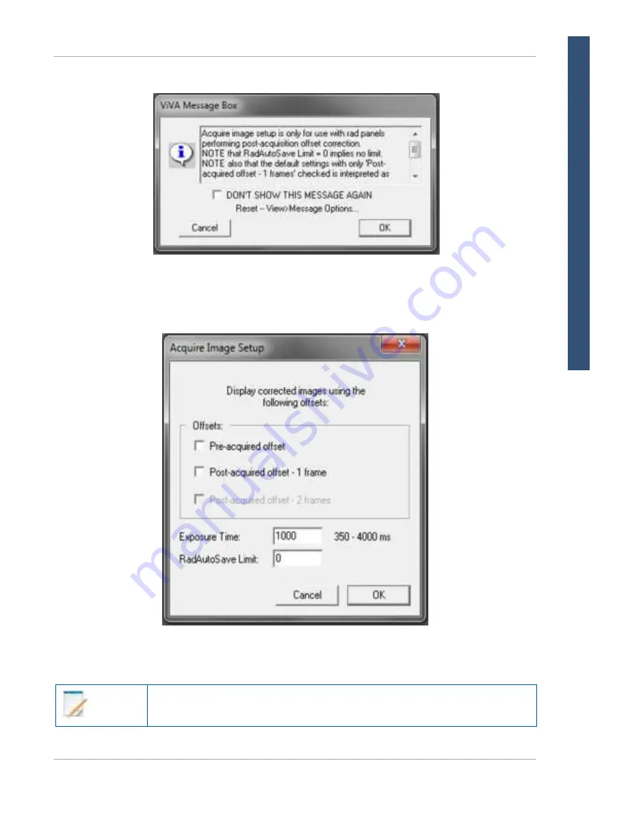
A message box will appear, click 

OK 

to proceed. 


Figure 55  Message Box 


Enter the 

integration time 

(exposure time) in the input box. Only values from 

350 - 4000 ms 

will be accepted. 


Figure 56  Enter Integration Time 


Note


 R

E

FE
RE

NCE


M

ANUAL


Содержание 2530W-G5

Страница 1: ...530W G5 X ray Detectors Before using the X ray detectors be sure to read this manual thoroughly along with any other manuals for the software and other system components Keep this manual where it is e...

Страница 2: ...storage must be performed in accordance with all applicable laws The user is also responsible for compliance to laws pertaining to the privacy of image data In no event is the X ray detector manufactu...

Страница 3: ...may result in personal injury death or product damage Keep this manual for future reference Meaning of Alerts and Notes DANGER This indicates a potentially hazardous situation which if ignored will r...

Страница 4: ...modify or alter the X ray detector its components or accessories Ignoring this warning may result in explosion fire or electric shock which may result in severe personal injury death or substantial p...

Страница 5: ...ient contact device and the surface shall not exceed 42 C Internal temperature sensor data is provided in the diagnostic data attached to each image These temperature measurements are well correlated...

Страница 6: ...X ray detector on the cable stepping on the cable pulling the cable or subjecting the cable to excessive bending or bundling Ignoring this warning may cause cable failure resulting in substantial pro...

Страница 7: ...nclosure or support structure Ignoring this caution may result in personal injury or damage to the product Caution Do not exceed the maximum uniform load weight of 300 kg distributed across the surfac...

Страница 8: ...tery before servicing and maintaining Do not touch the battery pack X ray detector cable connector or any other electrical component or equipment with wet hands Ignoring this warning may cause electri...

Страница 9: ...4336W G5 and 2530W G5 will not introduce noise An aftermarket power supply may not be used with the X ray detector WLAN WARNING Do not obstruct the X ray detector antenna If it is obstructed by metal...

Страница 10: ...ccess to the X ray detector and the WLAN access point Unauthorized access may cause disruption to the normal operation of the X ray detector and access point vTrigger Mode Automatic Exposure Detection...

Страница 11: ...on WARNING Turn off the power of the X ray detector see Section 11 7 when the inspections indicated in this manual are going to be performed Ignoring this warning may result in electric shock which ma...

Страница 12: ...Before You Begin 4343W 4336W G5 2530W G5 X ray Detectors xii www vareximaging com This page intentionally left blank...

Страница 13: ...s 13 11 0 Getting Started 16 11 1 Shipment Contents 16 11 2 Data Interface and Cables 16 11 2 1 Connecting the Service Cable for 4343W 17 11 2 2 Connecting the Tether Cable for 4336W G5 and 2530W G5 1...

Страница 14: ...on 42 11 12 4 Gain Calibration Steps 44 11 13 Image Acquisition 47 11 13 1 Acquiring Radiography Images 48 11 13 2 Radiographic Acquisition Settings 51 11 14 ViVA Configuration Settings 51 11 15 Dynam...

Страница 15: ...ions 69 16 2 Electromagnetic Immunity 70 16 3 Radio Frequency RF Compliance Information 76 16 3 1 United States FCC IC Compliance 76 17 0 Regulatory 79 17 1 Industry Canada Notice 79 17 2 Declaration...

Страница 16: ...Table of Contents 4343W 4336W G5 2530W G5 X ray Detectors xvi www vareximaging com This page intentionally left blank...

Страница 17: ...Acquisition 47 Table 15 Operational Mode Example 56 Table 16 Problems and Solutions 64 Table 17 4343W Radiated Conducted Emissions Harmonics Voltage Fluctuations Flicker 69 Table 18 4336W G5 and 2530...

Страница 18: ...List of Tables 4343W 4336W G5 2530W G5 X ray Detectors xviii www vareximaging com This page intentionally left blank...

Страница 19: ...Unlatch Battery 24 Figure 14 Battery Removal 24 Figure 15 Battery Charge Level 25 Figure 16 Varex Inductive Battery Charger Dimensions in mm and Mounting Hole Locations 4343W and 4336W G5 and 2530W G...

Страница 20: ...Drop Down Menu 48 Figure 43 Acquire Image Button 49 Figure 44 Acquire Image 49 Figure 45 Start Acquisition 50 Figure 46 Image Acquisition Progress 50 Figure 47 Acquisition Type Drop Down Menu 51 Figu...

Страница 21: ...Detector Dimensions in mm 84 Figure 64 4343W X ray Detector Dimensions in mm 84 Figure 65 4336W G5 X ray Detector Dimensions in mm 85 Figure 66 4336W G5 X ray Detector Dimensions in mm 85 Figure 67 2...

Страница 22: ...xxii www vareximaging com List of Figures 4343W 4336W G5 2530W G5 X ray Detectors This page intentionally left blank...

Страница 23: ...X ray system design It is the responsibility of the X ray system manufacturer to confirm safety efficacy and compliance of the X ray system intended for use inclusive of the X ray detector The Digita...

Страница 24: ...EQ Request SDK Software Developer Kit ViVA Varex Imaging and Viewing Application VSP Varex Smart Panel vTrigger Automatic Exposure Detection WLAN Wireless Local Area Network 6 0 References Table 2 inc...

Страница 25: ...l does not apply to model 2530W G5 IP68 The X ray detectors have an IP68 ingress protection rating It is completely protected against ingress of dust and has protection against full water immersion fo...

Страница 26: ...R EFERENCE M ANUAL 4343W 4336W G5 2530W G5 X ray Detectors Table 3 Definition of Symbols Continued Symbol Description Type B Applied Part Underwriters Laboratory Safety Mark China RoHS environmentally...

Страница 27: ...1 1 2008 Medical Electrical Equipment Part 1 General Requirements for Basic Safety and Essential Performance CAN CSA C22 2 No 601 1 M90 2005 Medical Electrical Equipment Part 1 General Requirements fo...

Страница 28: ...torage Transport Temperature ambient 20 C to 55 C Operating Temperature ambient 10 C to 40 C Storage and Operating Humidity Range non condensing 10 to 90 Atmospheric Pressure Range 70kPa to 106kPa Sho...

Страница 29: ...W G5 T2 Minimum 19 C T2 Maximum 47 C 2530W G5 T1 Minimum 19 C T1 Maximum 48 C Note The T1 4343W and T2 temperature sensors are used to monitor the internal temperature of the glass These are the only...

Страница 30: ...tor and the imaging system and may be mounted in an equipment enclosure or it may also be wall or ceiling mounted to maximize wireless signal strength A Service Cable is supplied with the 4343W to all...

Страница 31: ...16 bit 16 bit 16 bit Mechanical 4343W 4336W G5 2530W G5 Housing Plastic with Carbon Fiber entrance window Plastic with Carbon Fiber entrance window Plastic with Carbon Fiber entrance window Weight wit...

Страница 32: ...e The 2 4GHz frequency is not available for use with these detectors Do not use the 2 4GH band setting with the router or access point being used with the detector UNII 1 5150MHz 5250MHz UNII 3 5725MH...

Страница 33: ...1dBm 802 11n ac 40_5190MHz 9 1dBm 802 11n ac 40_5230MHz 9 1dBm 802 11n ac 40_5755MHz 5795MH z 9 1dBm 802 11ac 80 8 1dBm 802 11ac 80 10 5 1dBm 802 11ac 80 10 5 1dBm Transmit Power WIFI_Chain 1 802 11n...

Страница 34: ...ensitivity 802 11a 70dBm 54Mbps 802 11a 70dBm 54Mbps 802 11a 70dBm 54Mbps 802 11n 5GHz HT20 60dBm MCS7 802 11n 5GHz HT20 60dBm MCS7 802 11n 5GHz HT20 60dBm MCS7 802 11n 5GHz HT40 60dBm MCS7 802 11n 5G...

Страница 35: ...nd Features Number Description 1 Handles 2 Battery Alignment Marker 3 Battery and Battery Well 4 Replaceable Battery Latch 5 Antennas 6 Inductive Charging Receiver 7 Patient Contact Surface 8 Service...

Страница 36: ...nd Features Number Description 1 Handles 2 Battery Alignment Marker 3 Battery and Battery Well 4 Replaceable Battery Latch 5 Inductive Charging Receiver 6 Antennas 7 Patient Contact Surface 8 Tether C...

Страница 37: ...atures Number Description 1 Handle 2 Battery Alignment Marker and Contacts 3 Battery Well 4 Replaceable Battery Latch 5 Inductive Charging Receiver 6 Antennas 7 Tether Cable Connection 8 LED Status In...

Страница 38: ...es WARNING For proper operation X ray detector antennas and access point antennas should be unobstructed WARNING Access point should not be installed next to power supply or generator equipment Please...

Страница 39: ...g com 17 Figure 5 X ray Detector as Access Point Figure 6 X ray Detector with Router 11 2 1 Connecting the Service Cable for 4343W To connect the Service Cable 1 Pull back the USB door 2 Insert the Se...

Страница 40: ...e workstation by providing a 100Mbp s Ethernet connection for set up of the wireless interface and as a last resort for retrieval of images from the X ray detector in case of wireless transmission fai...

Страница 41: ...e for 4336W G5 and 2530W G5 To connect the Tether Cable 1 Remove the overlay to reveal the screw holding the USB door in place see Figure 8 Figure 8 Remove the Overlay 2 Completely remove the screw an...

Страница 42: ...net connection for tether communication set up of the wireless interface and as a last resort for retrieval of images from the X ray detector in case of wireless transmission failure Note The Tether C...

Страница 43: ...icrosoft Windows operating system Sample code C will also be provided to illustrate the sequence of API calls needed to acquire X ray images This will include sample code for the standard set of APIs...

Страница 44: ...to transfer a configuration file to the X ray detector This is a service function and should not be used by OEM customers Additionally transferring a new file to the X ray detector is typically only...

Страница 45: ...Chargers visit www vareximaging com 11 4 1 Battery Installation 1 Insert Battery at a slight angle so that the side with contacts sits over the adjoining contacts in the battery compartment Note When...

Страница 46: ...ray Detectors 11 4 2 Battery Removal 1 Press in the battery latch until an audible click is heard The latch will stay in closed position 2 Place a finger in opening on either side of the latch and lif...

Страница 47: ...ate Each LED illuminated represents 25 charge Figure 15 Battery Charge Level 11 4 4 Battery Hot Swap The X ray detectors are equipped with a hot swappable battery When a discharged battery is removed...

Страница 48: ...he Varex Inductive Battery Charger and Detector Support into the bucky tray Use Figure 16 Figure 17 and Figure 18 for mounting locations 3 Route the USB C Cable from the Varex Inductive Battery Charge...

Страница 49: ...343W 4336W G5 2530W G5 X ray Detectors www vareximaging com 27 Figure 16 Varex Inductive Battery Charger Dimensions in mm and Mounting Hole Locations 4343W and 4336W G5 and 2530W G5 R EFERENCE M ANUAL...

Страница 50: ...2530W G5 X ray Detectors 28 www vareximaging com R EFERENCE M ANUAL Figure 17 VHB Tape Placement Locations on Varex Inductive Battery Charger Figure 18 VHB Tape Placement Dimension on Varex Inductive...

Страница 51: ...ng a third party Inductive Battery Charger WARNING Third party Inductive Battery Chargers must not be used in the bucky tray Ignoring this warning may result in image artifacts or damage to the X ray...

Страница 52: ...n battery is inserted Note When a Battery is inserted into the X ray detector the LED Status Indicator will turn orange as it boots After booting it connects to the configured wireless router and is i...

Страница 53: ...To reboot 1 Remove the tether cable 2 Insert and remove the Battery 4 times within an 8 second window see Figure 20 Figure 20 Reboot Sequence WARNING The tether cable must be removed before attemptin...

Страница 54: ...nge Solid 111111 Booting Green Blinking 100000 No connection to the detector blinks every 1 5 seconds Green Blinking 101010 Connected to the detector blinks twice 2 per second Green Solid 111111 Link...

Страница 55: ...nge then begin to blink Green See Table 12 2 To link to the X ray detector click the ViVA icon to launch the application Figure 22 The ViVA Icon 3 The X ray detector will link automatically in ViVA Wh...

Страница 56: ...odes file Reset software to Factory Image Note Control Panel screens will vary slightly for the type of detector WiFi related settings will only display for wireless detectors Note For best results on...

Страница 57: ...er Name and Password 3 Enter the default user and password User Name admin Password password 4 Click Log In Note Once the X ray detector is configured the default password should be changed 5 The main...

Страница 58: ...ings To modify the settings 1 Click Settings 2 The Settings content will load and any settings that are able to be modified 3 After inputting desired settings click Update The X ray detector will rebo...

Страница 59: ...long with its matching confirmation click Change to confirm the new password 4 To clear the passwords entered in the forms click Reset Figure 27 Change Password Note Passwords must be at least 8 chara...

Страница 60: ...are 1 Click Update Firmware This option is used to update all X ray detector software embedded software firmware etc 2 Select the Varex provided firmware image by clicking Browse 3 After selecting the...

Страница 61: ...was successful At this point the X ray detector will apply the updated firmware Figure 29 Firmware Updated WARNING A fully charged battery should be used during firmware update Do not remove the batte...

Страница 62: ...fixed pattern pixel intensity variations in the image associated with the dark current and electronic offsets The Offset reference image is an average of a series of frames acquired without X ray and...

Страница 63: ...Calibration from the menu bar under Acquisition Figure 31 Initiate Offset Calibration 3 A Calibration Setting window appears 4 Enter the number of frames desired and click OK Figure 32 Calibration Se...

Страница 64: ...ss will include automatically running an Offset calibration to ensure that the detector is properly calibrated Gain calibration is based upon the linear response of the X ray detector to dose Normaliz...

Страница 65: ...usted under the Mode Settings pull down menu Note We recommend accumulating 32 frames for gain calibration and 8 frames for offset calibration for optimal image quality Note Gain calibration should be...

Страница 66: ...referred to as dark field acquisition Note X rays must not be used for this part of the calibration Gain Calibration Multiple Gain frames taken Software pauses at each frame so that the operator can...

Страница 67: ...tion Progress window will appear When prompted waiting for X ray perform exposure Figure 37 Gain Calibration Progress window 4 Once all X ray frames have been accumulated the calibration process will...

Страница 68: ...L Figure 39 Gain Calibration Complete Note Gain calibration should be performed at regular intervals At least every twelve 12 months If the central beam of the X ray source has been moved relative to...

Страница 69: ...applied during Acquisition Type Images transferred to Workstation Raw Exposed Frame and Post Offset Frame Corrected A single fully corrected frame Offset Corrected A single offset corrected frame with...

Страница 70: ...es for diagnosis Note The OEM workstation should have the ability to employ the PREP and Expose_OK signals See Section 13 3 or Section VSPADU UTILITY in 03236 FP2032_VarexSmartPanel_SoftwareInterfaceS...

Страница 71: ...4336W G5 2530W G5 X ray Detectors 3 Click Acquire Image button or click Acquire Image in the Acquisition menu under the Menu Bar to begin acquiring images Figure 43 Acquire Image Button Figure 44 Acq...

Страница 72: ...appear Click Start Acquisition and initiate X ray exposure Figure 45 Start Acquisition 5 The Radiographic Acquisition Progress window will begin to show acquisition process with a blue status bar Fig...

Страница 73: ...k the Acquisition Type Drop Down Menu to switch between Software or Hardware Acquisition vTrigger Figure 47 Acquisition Type Drop Down Menu 11 14 ViVA Configuration Settings This section describes the...

Страница 74: ...ware Handshaking click Acquisition under the Menu Bar and select or de select Hardware Handshaking ViVA will remember your preferences for future launches Hardware Handshaking is needed for gain calib...

Страница 75: ...e System Settings click Acquisition under the Menu Bar 4 Click on System Settings A System Settings window will appear Image and calibration settings may be turned On or Off in this window Figure 51 O...

Страница 76: ...15 Dynamic Integration Settings Dynamic Integration allows the User to change the exposure time settings within ViVA 1 Click the desired mode from the Mode Drop Down Menu Figure 53 Select Mode 2 Click...

Страница 77: ...is selected or the link has been closed 4343W 4336W G5 2530W G5 X ray Detectors 3 A message box will appear click OK to proceed Figure 55 Message Box 4 Enter the integration time exposure time in the...

Страница 78: ...or more information on how to dynamically change the integration time The X ray detector supports Radiographic and vTrigger modes of operation see Table 15 for a typical mode example The sensitivity o...

Страница 79: ...time is defined in the customer configuration file and may be different for each mode APIs can be used to obtain several of the configuration file mode settings When trigger is called the software se...

Страница 80: ...EM the benefit of not requiring any hardware synchronization with the generator A vTrigger acquisition mode utilizes the X ray detector s hardware to sense when X rays are exposed to the X ray detecto...

Страница 81: ...and hand switch and relay those signals to the various API calls in the VSP Library Upon receiving PREP signal the workstation software should call the Prepare API function upon receiving REQ signal...

Страница 82: ...be transferred to a client PC later The detector can be armed in the autonomous mode and then taken to the patient s room In the process the detector link will be closed and remain in the armed state...

Страница 83: ...X ray grade carbon fiber input window and housing WARNING When the X ray detector system is going to be cleaned or disinfected be sure to remove the battery pack Ignoring this warning may result in ex...

Страница 84: ...ident after air drying remove the residue with a general Isopropyl Alcohol wipe and let air dry 14 1 3 Disinfecting the X ray Detector To disinfect the X ray detector 1 Remove the battery from the X r...

Страница 85: ...RNING Do not use flowing liquid or immersion on the X ray detector battery battery compartment or battery charger 14 2 Field Replaceable Parts The X ray detector has been designed to allow for field r...

Страница 86: ...nsure they match 5 If problem persists consult the manufacturer or field service technician for help Intermittent or slow WiFi connection or slow image transfer Check the router band setting band shou...

Страница 87: ...oblem persists consult the manufacturer or field service technician for help Acquired image shows a white or a black channel 1 Let power off Section 11 7 or reboot the detector Section 11 8 re insert...

Страница 88: ...al or horizontal lines 1 Let power off Section 11 7 or Reboot the detector Section 11 8 re insert the battery re establish the link 2 Ensure that the tube dose is set to the correct settings 3 Acquire...

Страница 89: ...ame AppData Local crashdumps viva log Detector dropped 1 Power off the detector Section 11 7 and inspect for damage 2 If the battery does not appear damaged place into battery charger to see if batter...

Страница 90: ...been exposed to high energies 8 5 MeV or higher Varex cannot accept any activated X ray detectors that have been used in environments 8 5 MeV or higher that exceed the local regulatory limits WARNING...

Страница 91: ...and displayed is acceptable e g small amount of noise pixelation video artifact etc if the degradation would not affect the diagnosis or treatment Images acquired shall be normal when the immunity int...

Страница 92: ...poses Voltage fluctuations flicker emissions IEC 61000 3 3 Complies Complies The detector is suitable for use in all establishments other than domestic and those directly connected to the low voltage...

Страница 93: ...inued operation during power mains interruptions it is recommended that the system be powered from an uninterruptible power supply or a battery Power frequency 50 60 Hz magnetic field IEC 61000 4 8 30...

Страница 94: ...1845 1970 1700 1990 GSM 1800 CDMA 1900 GSM 1900 DECT LTE Band 1 3 4 25 UMTS Pulse modulation b 217 Hz 2 0 3 28 2450 2400 2570 Bluetooth WLAN 802 11 b g n RFID 2450 LTE Band 7 Pulse modulation b 217 H...

Страница 95: ...5 kV 1 kV 2 kV Line to Ground 0 5 kV 1 kV Line to Line 0 5 kV 1 kV 2 kV Line to Ground Mains power quality should be that of a typical professional healthcare environment Voltage dips short interrupti...

Страница 96: ...m 80 MHz to 2 7 GHz 80 AM at 1 kHz E 6 P d Where P is the maximum power in W d is the minimum separation distance in m and E is the Immunity Test Level in V m If the X ray detector complies with Immu...

Страница 97: ...duty cycle square wave signal As an alternative to FM modulation 50 pulse modulation at 18 Hz may be used because while it does not represent actual modulation it would be worst case Note These guide...

Страница 98: ...quipment is operated in a commercial environment This equipment generates uses and can radiate radio frequency energy and if not installed and used in accordance with the instruction manual may cause...

Страница 99: ...table RF exposure limit set forth for an uncontrolled environment and are safe for intended operation as described in this manual The further RF exposure reduction can be achieved if the product can b...

Страница 100: ...4343W 4336W G5 2530W G5 X ray Detectors 78 www vareximaging com R EFERENCE M ANUAL Figure 61 4336W G5 Detector and Wireless Label Locations Figure 62 2530W G5 Detector and Wireless Label Locations...

Страница 101: ...ette derni re n mette pas de champs radio lectriques sup rieurs aux limites specif es par Sant Canada pour le grand public consulter le Code de s curit 6 disponible sur le site Web de Sant Canada l ad...

Страница 102: ...se requirements set a SAR limit of 1 6 W kg averaged over one gram of tissue The highest SAR value reported under this standard during product certification for use when properly worn on the body is 1...

Страница 103: ...e el Radiolan cumple con los requisitos esenciales y cualesquiera otras disposiciones aplicables o exigibles de la Directiva 1999 5 CE Greek Varex Imaging Radiolan 1999 5 Fran ais French Par la pr sen...

Страница 104: ...lo ili direktive 1999 5 ES Slovensky Slovak Varex Imaging t mto vyhlasuje e Radiolan sp a z kladn po iadavky a v etky pr slu n ustanovenia Smernice 1999 5 ES Suomi Finnish Varex Imaging vakuuttaa t te...

Страница 105: ...ce Cable 149961 6 5 ft 2 2m Field Maintenance Kit 151236 N A Mains Hospital Grade 110V Cable 11616 6 5 ft 2m Mains European Cable 660 8 2 ft 2 5m Mains Chinese Cable 19045 8 2 ft 2 5m Note Accessory o...

Страница 106: ...X ray Detectors 84 www vareximaging com R EFERENCE M ANUAL 19 0 Appendix B Mechanical Drawings All dimensions are measured in mm Figure 63 4343W X ray Detector Dimensions in mm Figure 64 4343W X ray D...

Страница 107: ...4343W 4336W G5 2530W G5 X ray Detectors www vareximaging com 85 Figure 65 4336W G5 X ray Detector Dimensions in mm Figure 66 4336W G5 X ray Detector Dimensions in mm R EFERENCE M ANUAL...

Страница 108: ...4343W 4336W G5 2530W G5 X ray Detectors 86 www vareximaging com R EFERENCE M ANUAL Figure 67 2530W G5 Detector Dimension in mm Figure 68 2530W G5 Detector Dimension in mm...

Страница 109: ...Firmware 34 Firmware Update 38 G Gain Calibration 42 Gain Calibration Steps 44 H Hot Swap Battery 25 How To Access Control Panel 34 Acquire Image 47 Gain Calibration 44 Link 33 Offset Calibration 40...

Страница 110: ...x Safety For Your iii Screws Inductive Charger 27 Sensor Temperature 7 Service Change Password 37 Firmware Update 38 In Warranty 68 Log In 34 Maintenance 61 Obtain RMA Number 68 Out of Warranty 68 Rep...

Страница 111: ...4343W 4336W G5 2530W G5 X ray Detectors This page intentionally left blank 89...

Страница 112: ...obal offices visit www vareximaging com 2021 Varex Imaging All rights reserved The Varex Imaging logo and design are registered trademarks of Varex Imaging or its subsidiaries in the United States and...

Отзывы: