Vanner VLT12-600 Скачать руководство пользователя страница 14

VANNER


Incorporated

VLT Series True Sine Wave Inverter - Owner’s Manual

14

AC Output Wiring Installation Procedure

WARNING: Before proceeding with the AC wiring, verify that the inverter is OFF and that the inverter

is NOT connected to the battery. Serious or fatal electrical shock may occur.

1. The wiring of your inverter installation should conform to the National Electric Code (NEC) and any other

state or local codes in effect at the time of installation.  These codes have been written for your protec-
tion and their requirements should be followed

2. Route the AC output wiring, and DC power wiring, with as much physical separation as possible from

low voltage wiring such as audio and video signal wires.

3. Verify AC wiring installation. Verify that all connections are tight. Secure all wiring.

Start-up and Test Procedure

After the inverter has been properly mounted with sufficient ventilation, DC cables have been connected to the
inverter (but not yet to the battery), AC wiring has been completed, and all remote connections have been
checked; the Start-up and Testing procedure should be performed.

WARNING: These procedures are to be performed only by a QUALIFIED INSTALLER.

Inverter Start-up and Testing

1. Place the Inverter ON/OFF switch in the OFF position.

2. Place any remote switches in the OFF position.

3. Verify that any external AC output circuit breakers and GFCI receptacles are reset.

4. Connect the battery to the inverter. 

BE AWARE

, as a quantity of capacitors become charged upon

completing the DC circuit, 

THERE WILL BE A LARGE SPARK

 when the last connection is made.

5. Turn the inverter ON and use a test load (75 watt trouble light) plugged into the 15 amp GFCI recep-

tacle to verify the inverter produces AC power.

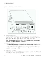
6. Refer to the description of operation of the indicator lights, Section 2, items 4 through 10 to follow and

verify correct inverter operation.

7. If the inverter is not operating as described, see Trouble Shooting Procedures.

Содержание VLT12-600

Страница 1: ...rter VLT12 600 VLT12 1000 VLT12 1500 VLT24 600 VLT24 1000 VLT24 1500 VLT48 1000 VLT48 1500 Owner s Manual D910106 Rev B Rev May 24 2007 60Hz Models VLTE12 600 VLTE12 1000 VLTE12 1500 VLTE24 600 VLTE24...

Страница 2: ...ies True Sine Wave Inverter Owner s Manual 2 Vanner Incorporated 4282 Reynolds Drive Hilliard OH 43026 800 AC POWER 800 227 6937 Tel 614 771 2718 Fax 614 771 4904 www vanner com e mail sales vanner co...

Страница 3: ...cator 11 Overload Indicator 11 ON OFF Switch 11 Inverter Indicator Light 11 GFCI Duplex Receptacle 11 Section 5 Installation and Setup 12 Unpacking the Inverter 12 Inverter Installation Considerations...

Страница 4: ...liarize yourself with the model numbers of the inverter and optional accessories you have purchased before proceeding with this manual If you require additional information please contact your dealer...

Страница 5: ...attery Shutdown Over Temperature Shutdown Overload Inverter ON OFF Indicator Overload Short Circuit Reverse Polarity fuse Over Under Input Voltage OverTemp Inverter may be mounted in any orientation M...

Страница 6: ...ed cooling intake fan Definitions Load Demand Feature and Load Demand Mode The Load Demand Feature is an energy conserving feature which allows the inverter to enter the Load Demand Mode whenever the...

Страница 7: ...nt fire or explosion DO NOT install in confined areas or compartments that contain batteries or flam mable materials WARNING Improper use of this product may result in risk of electrical shock Both AC...

Страница 8: ...ries or flammable materials or in locations that require ignition protected equipment This includes any space containing gasoline powered machinery fuel tanks or joints fittings or other connections b...

Страница 9: ...Rear entry for negative DC input cable 2 Rear entry for positive DC input cable 3 Rear entry for Remote Control RS 232 Connection 4 Chassis Ground Bonding Lug 5 Cooling Fans Draw air in through intake...

Страница 10: ...light is in the red areas of the graph the inverter may shut itself OFF 7 Load Watt Indicator The AC load watt bar graph indicates the power drawn from the inverter It will indicate wattage by loads...

Страница 11: ...F switch to the OFF position correct the fault condition and turn the inverter back ON 12 ON OFF Switch and RESET Switch The ON OFF Switch is a two position rocker switch used to turn the inverter ON...

Страница 12: ...se the battery cables are connected backward reverse polarity 2 The wiring of your inverter installation should conform to the National Electric Code NEC and any other state or local codes in effect a...

Страница 13: ...location should be within 18 of the battery and accessible for visual inspection and replacement If possible locate so the last DC connection can safely be made at the fuse 4 Prepare DC cable ends 5...

Страница 14: ...sufficient ventilation DC cables have been connected to the inverter but not yet to the battery AC wiring has been completed and all remote connections have been checked the Start up and Testing proce...

Страница 15: ...ble Shooting Procedures The following are the most common questions heard by Vanner service professionals If your situation does not apply to the following categories please contact your local Vanner...

Страница 16: ...ove obstructions from air exhaust vents and cooling fan Problem Overload Indicator Light is ON when AC load is applied Check Verify AC load is within the inverter s rated capacity Remove excessive loa...

Страница 17: ...CI Test Record For maximum protection against electrical shock hazard operate the Test Switch on the Ground Fault Circuit Interrupter at least once a month and record the values in this supplied table...

Страница 18: ...nverter Owner s Manual 18 Vanner Incorporated 4282 Reynolds Drive Hilliard OH 43026 800 AC POWER 800 227 6937 T e l 614 771 2718 Fax 614 771 4904 www vanner com e mail sales vanner com Copyright 2007...

Отзывы: