


VANNER
Incorporated
VLT Series True Sine Wave Inverter - Owner’s Manual
13
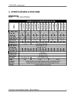
VLT12-600
VLT12-1500
VLT24-1000
VLT12-1000
VLT24-600
VLT24-1500
Model #
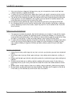
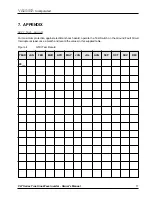
7.
Proper DC cable size is critical
for the performance and safe operation of the inverter system. The
minimum recommended cable size allows a ½ volt maximum voltage drop at maximum inverter capacity
and will insure optimum inverter performance. Quick DC cable connectors are available.
8.
Do not use the vehicle chassis as the DC negative conductor. The negative cable should be the same size
as the DC positive cable and should be connected directly to the battery negative terminal.
9.
DC cables should be as short as possible (no longer than 15 feet to prevent performance loss).
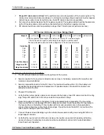
VLT Series DC Cable and Fuse Sizing Chart
Distance (positive cable length) from battery to Inverter: 20’ maximum length.
Chart is based on negative cable being same length as positive cable.
The recommended cable size holds voltage drop to 05vdc max at full load.
DC Wiring Installation Procedure
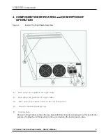
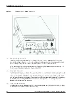
1. The DC wiring terminals are located on the right rear of the inverter.
2. Select a location for the inverter. An ideal location is close to the battery; protected from weather and
moisture; and well ventilated.
3. Select an accessible location for the DC Fuse. The location should be within 18” of the battery and
accessible for visual inspection and replacement. If possible locate so the last DC connection can
safely be made at the fuse.
4. Prepare DC cable ends.
5. Verify that the battery positive cable is not connected to the battery. Insert DC cables into the DC wiring
lugs. Torque DC cable bolts to 50 inch pounds. Re-torque after 30 days.
6. Route the negative DC cable to the battery. Verify cable polarity before proceeding. The fuse will be
blown and inverter can be damaged if the DC cables are reversed. Route the positive DC input cable to
the fuse and then to the battery. Protect cables with loom and use grommets or other appropriate
means where cables may contact hard, sharp edges. If possible, make the last DC connection at the
fuse to avoid causing a spark at the battery.
7. Connect Chassis Ground Bonding Lug to the vehicle chassis and/or earth ground using AWG No.8 or
larger copper conductor.
8. Verify that the inverter will turn ON but do not leave the inverter connected to the battery at this time
(remove the fuse). Final battery connections will be made after all control and AC output installation
issues have been inspected.
Cable Size
Mega Fuse Holder
Mega Fuse PN
Fuse Size (Amps)
10.0
20’
20’
20’
6 ga
4 ga
2 ga
1 ga
1/0
20’
20’
20’
20’
20’
20’
20’
20’
16.0
12.0
NR
12.0
NR
8.0
20’
20’
20’
20’
20’
20’
20’
16.0
NR
11.0
14.0
18.5
80
60
80
150
200
100
013910
013909
010098
013914
013910
013910
011876
011876
011876
011876
011876
011876


