14
Setup
Setup
Setup
Setup
Setup
15
Setup
Setup
Setup
Setup
Setup
13.
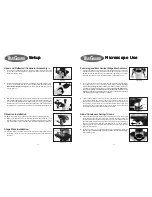
If it is not well focused use the main focus controls to bring it in so. Set the
iris opening to where it almost completely fills the field of view (figure 25).
Reflected Field Diaphragm Alignment
(continued)
Figure 25
Figure 26
Figure 27
Figure 28
Figure 29
14.
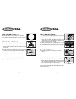
If the iris is not properly centered in the field then use the two included 3mm
hex wrenches to center it. Place one into each of the access holes located
on either side of the reflected illuminator (figure 26). Make sure they
completely engage the hex screws located within.
15.
While looking at the field diaphragm silhouette through the eyepieces, rotate
the two hex wrenches back and/or forth until the diaphragm is properly
centered (figure 27). You can make adjustments to the diaphragm using
the Field dial in order to aid in this process.
Eyecups
(optional)
16.
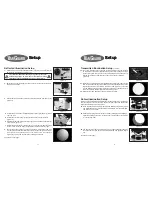
The rubber eyecups can be mounted to the eyepieces (figure 28) in order to
prevent stray light from entering and therefore providing a higher contrast
image. Eyeglass wearers who choose to wear their glasses during
microscope use should remove the eyecups in order to maintain proper
eyepoint positioning to the eyepiece. You will want to be careful not to make
contact between the eyepiece lenses and your eyeglasses to protect the
delicate optical coatings though.
Interpupilliary Adjustment
17.
Place a specimen on the stage and while looking through the eyepieces fold
the eyetubes together or further apart (figure 29) to make the two images
converge into one field of view. This adjustment will be different for all users
and should be checked and readjusted before each use.
Focus Adjustment
18.
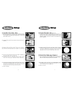
Focusing on your specimen is achieved through rotating the coarse and/or
fine focusing knobs. These are located on either side of the stand in a coaxial
layout (figure 30). The outer-most dials control the fine focus and the larger
dials located just inward control the coarse focus adjustments.
19.
The inner-most dial located on the left focus adjustment (figure 31) controls
the stage movement tension. This should be adjusted to where the focus
controls are smooth and easy to turn but not so loose that the stage drifts
out of focus.
Focus Tension Adjustment
Figure 30
Figure 31
Figure 32
Figure 33
Figure 34
Stage Limit
20.
Located inward of the right hand coarse focus adjustment (figure 32) is the
stage limit which prevents the stage from crashing into the objectives.
Diopter Adjustment
22.
Before each use of the microscope it’s important to check and readjust the
diopter if necessary. With the main focus controls, and viewing only with
your right eye, bring the specimen into focus. Then view the image using
only your left eye and rotate the diopter ring located around the left eyetube
(figure 34) to bring the image into focus.
21.
To adjust, first unlock the limit by rotating it counter-clockwise (figure 33).
With the highest power objective in the light path adjust the stage until the
image through the eyepieces is in focus then lock the limit by rotating the
control clockwise until tight (figure 33). The upward motion of the stage
when using the coarse focus controls is now limited to this point. The fine
focus controls are not affected though and will still allow upward movement
of the stage.
right side
focus
controls
left side
focus
controls
tension
dial
eyecups
stage limit
unlock
lock
diopter
left adjustment
right adjustment


