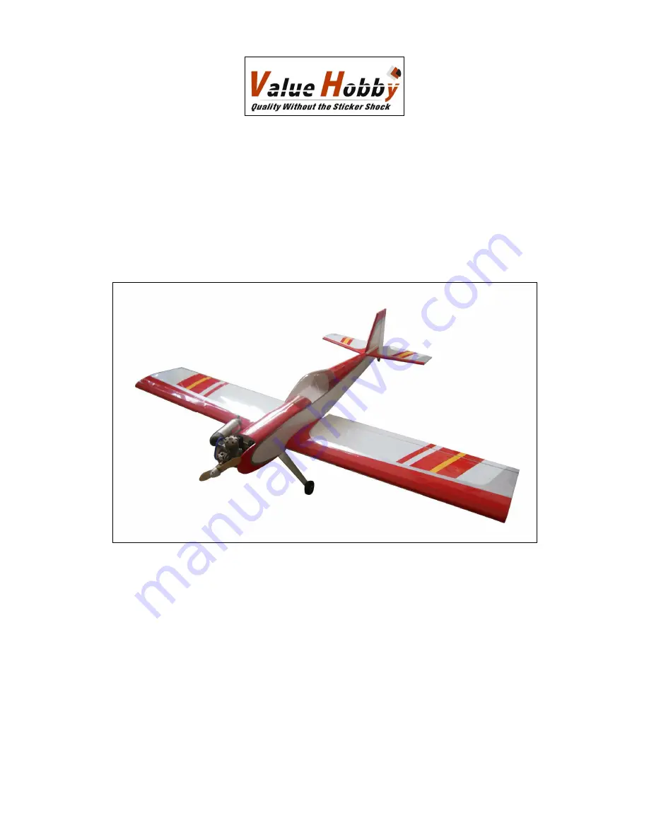
Value Hobby Stylus Sport 60 Скачать руководство пользователя страница 1


Stylus Sport 60

Stylus Sport 60

Stylus Sport 60

Stylus Sport 60    

Almost-Ready-to-Fly 

Instruction Manual 


Specifications 

Wingspan: 70.9 in (1800mm) 

Length: 56.2in (1428mm) 

Wing Area: 795.1sq in (51.3sq dm) 

Flying Weight (GP): 7.28lbs (3300g) 

Flying Weight (EP): 6.72lbs (3050g) 


Содержание Stylus Sport 60

Страница 1: ...60 Stylus Sport 60 Stylus Sport 60 Almost Ready to Fly Instruction Manual Specifications Wingspan 70 9 in 1800mm Length 56 2in 1428mm Wing Area 795 1sq in 51 3sq dm Flying Weight GP 7 28lbs 3300g Fly...

Страница 2: ...e Hobby reserves the right to modify this warranty without notice Value Hobby has no control over the final stages of assembly or the material used for the final assembly No liability shall be assumed...

Страница 3: ...he first time you take the plane out to the flying field These wrinkles are the result of wood shrinkage and or expansion Balsa wood changes size and shape slightly as it is exposed to varying humidit...

Страница 4: ...ed Control 80A Brushless ESC 1 Recommended Battery LiPO GForce 40C 3300mAh 4S 14 8V LiPO 1 Prop Size 14 X 7 or 15 X 6 1 Servos Standard servos 5 nitro 4 electric Y Harness Universal Servo Y Harness 30...

Страница 5: ...chine screw M4 35mm 1 4in 2pcs Locknut M4 4pcs Pack4 Self tapping screws M2 5 8mm 3in 4pcs Wing bolt plate 2pcs Philips roundhead screw M4 35mm 1 4in 2pcs Washer 4 2pcs Pack5 Servo hatch 2pcs Servo mo...

Страница 6: ...down Use the thin CA to saturate the hinges Step4 Repeat the previous step to finish the right aileron installation Section 2 Aileron Servo Installation Required parts and hardware Wing panels Servo...

Страница 7: ...ill two holes on the hatch as shown The location for the holes should be in the central point of the blocks Step5 Use two M2 5 8mm 3in self tapping screws to secure the block wont loose Step6 Use four...

Страница 8: ...n Linkage Installation Required parts and hardware Aileron Servo pushrod 1 8 150mm 5 9in 2pcs Keeper 2pcs Clevis 2pcs Control horn 2pcs Nut plate 2pcs Philips roundhead screw M2 16mm 6in 4pcs Step1 Th...

Страница 9: ...rvo Step6 Repeat the step 11 to 14 to finish the other aileron servo installation Section 4 Wing Installation Required parts and hardware Wing panels Wing joiner 1pcs Wing bolts plate Philips roundhea...

Страница 10: ...Use a drill bit or screwdriver to locate the mounting holes as shown Step7 Align the hole on the plate to the hole on the wing as shown and use a felt tipped pen to trace the outline of the wing bolt...

Страница 11: ...the fuselage Step3 Push the stabilizer against the fuselage and use a felt tipped pen to trace the outline of the fuselage Step4 Use a hobby knife to trim the covering inside the lines drawn in the pr...

Страница 12: ...nto the elevator Slide the elevator and stabilizer together through the hinges Align the elevator tips with the stabilizer tips Once satisfied use a felt tipped pen to mark the location for the other...

Страница 13: ...Align one stock with the edge of the fin Use a felt tipped pen to trace the stock on the fin Step2 Use a hobby knife and a ruler to trim the covering along the line drawn in the previous step Step3 Re...

Страница 14: ...bare wood of the horizontal stabilizer and the bottom of the fin as shown Step8 Glue the fin onto the horizontal stabilizer Note use a square to make sure that the fin is perpendicular to the horizon...

Страница 15: ...dder Servo and Linkage Installation Required parts and hardware Pushrod 1 8 900mm 35 4in 2pcs Clevis 2pcs Control horn 2pcs Nut plate 2pcs Phillips roundhead screw M2 16mm 6in 4pcs Pushrod connector 2...

Страница 16: ...ly 360cc Engine mount 1 pair Phillips roundhead screw M4 25mm 1 0in 4pcs Washer 4 4pcs Step1 Attach the engine to the firewall with four M4 25mm 1 0in roundhead screws Step2 Position the engine on the...

Страница 17: ...uld extend out 13mm beyond the stopper and the vent line should be bent upwards and left uncut With the tubes installed in the stopper the stopper plates loosely in place with the PM3x25mm screw to ho...

Страница 18: ...drill the holes for mounting the electric motor Step3 Install the electric motor to the motor mount with the screws provided with the motor Section 11 Landing Gear Installation Required parts and har...

Страница 19: ...tapping screws Install the canopy to the fuselage as shown Section 11 Setting CG and Control throws Recommended CG For the first flights the recommended Center of Gravity location is 91mm 3 6in behind...

Страница 20: ...www valuehobby com stylus sport 60 html 20 www valuehobby com 2012 11 6...

Отзывы: