Manuale di Installazione e Manutenzione unità di recupero calore ad altissima efficienza -
Very high efficiency heat recovery unit
pag. 26
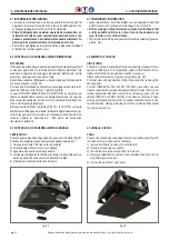
4.2 COLLEGAMENTO ALIMENTAZIONE UNITÀ
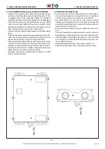
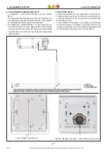
• Le connessioni e i cavi usati per esse sono a cura di chi installa
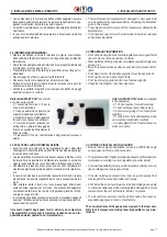
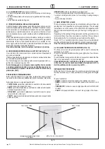
fig.13).
• Per l’alimentazione dell’unità base usare un cavo a 3 poli (linea, neu-
tro e terra) facente capo ad un connettore femmina C13 da innestare
sul corrispondente maschio incassato sull’unità base.
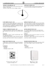
• Per l’installazione a parete dell’interfaccia non è necessaria una sca-
tola ad incasso, dato lo spessore esiguo; tuttavia si può utilizzare
anche una scatola da due moduli. Per fissarla alla parete utilizzare
2 opportuni fisher con viti attraverso le asole presenti nella placchetta
posteriore (fig.13).
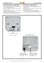
Asole di fissaggio -
Mounting holes
Batteria al litio (placchetta rimossa) -
Lithium battery (socket removed)
4 - COLLEGAMENTI ELETTRICI
4 - ELECTRIC CONNECTIONS
fig. 13
4.2 UNIT POWER SUPPLY
• Connections and cables have to be supplied by the installer (fig. 13).
• For basic unit power supply use a 3-wire cable (line, neutral, ground)
headed by C13 female connector to be inserted on the corresponding
built-in male connector.
• For the installation of the interface, only if needed, use a two module
flush mounted wall box. The interface is very thin and usually it is not
necessary to install the box. Fix it to the wall by two appropriate fisher
with screws through the eyelets in the rear socket (fig.13).

