


2
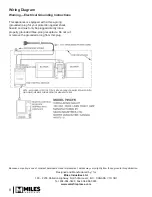
Fan Kits Components
The complete 795CFK kit contains the
following:
•
Fan enclosure: fan and motor unit,
control wire;
•
Fan control module;
•
Wiring diagram label;
•
6-foot power cord.
Kit 795CFK (as supplied)
Install the fan
We highly recommend to install this fan (blower) kit
to the appliance before installing the appliance in the
fireplace cavity. Otherwise, the appliance must be
disconnected and taken out of the cavity completely as
the fan can only be fitted from the rear.
NOTE:
The fan box adds 3 inches to the depth of the
appliance.
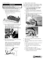
1.
Fit the fan to the appliance.
a) On the back of the appliance, remove the sheet
metal plate (9 screws) and discard it.
b) Reach through the fan mounting hole and apply
the self-adhesive
wiring diagram label
provided to the
rear side of the fan
access panel as
shown.
6-foot
electrical cord
Fan control wire
(module to receiver)
Wiring diagram
Fan control module
Fan enclosure
Note: the fan access panel is accessible from
the inside of the firebox for servicing (780
only)—see servicing section.
c) Remove the left side valve access panel (5
screws).
d) Unpack the fan
contents. From
the back of the
appliance, route
the fan control
wire from the fan
control module
to the remote
receiver inside
the appliance
case’s left side.
e) Insert the bottom
edge of the fan enclosure inside the edge of
the appliance box. Secure the fan box with the
screws removed in 1 (9 screws).
NO
TE - ALL WIRING IS
SPECIFIC T
O THIS KIT AND SHOULD ONL
Y BE REPL
ACED WITH
ORIGINAL EQU
IPMENT WIRING FR
OM THE MAN
UF
ACTURER


