Valor Legend 936XN Скачать руководство пользователя страница 4


4

13 

7

/

8

35”

71

1

/

4

47

5

/

8

84”

120

1

/

4

Height 
from
floor to 
center
of vent 
duct

Horizontal length from vent

elbow center to outside face of wall

2 kits required

1 kit required

No kit 
required

(Minimum distance to inside wall face 7”)


WITH PEDESTAL BASE 


13 

7

/

8

35”

71

1

/

4

46”

82

3

/

8

118

5

/

8

Height 
from
floor to 
center
of vent 
duct

Horizontal length from vent

elbow center to outside face of wall

2 kits required

1 kit required

No kit 
required

No kit required

1 kit required

(Minimum distance to inside wall face 7”)


WITH LEGS


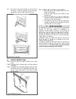
  Fig.1 Possible vent positions - Permissible positions 
within shaded area only


Operated  by a variable speed controller, it is 
designed to boost the natural convection 
process through the stove. It may be fitted 
before the stove is installed or retrofitted at a 
later date. 

#905 VEK 

Vent extension kit 


Designed to give a greater range of venting 
configurations. See venting graph figure 1 for 
the available configurations. Use of these 
kits will allow the stove to be sited in a 
basement provided that the terminal is above 
ground. 

#925HACK 

High altitude conversion kit. (For 936XN only) 


Required fo r installations between 2000ft 
and 4500ft. Consists of an exchange 
regulator and associated connectors. 


2. 

GENERAL


These appliances are certified by International Approval 
Services for use in Canada and the USA. The appliance 
are for installation directly venting through an outside wall. 
The appliances are for use only with the type of gas 
indicated on the rating plate. The appliances comply with 

CGA P.4.1, Testing method for measuring annual fireplace 
efficiencies.


 The installation must conform with  local codes or, in the 
absence of local codes, with the 

National Fuel Gas Code, 

ANSI Z223.1

 or the 

Canadian installation code     

CAN/CGA-149

. Only qualified licensed or trained 

personnel should install the appliance.  

2.1 

Rating plate


The rating plate is  located inside the control 
compartment door. 

2.2 

Rates (Btu/h)


936 XN 

936 XP 


Altitude 

(Ft)* 

Max. 

Min. 

Max. 

Min. 

Input 

0-2000 

27,000 

7,800 

20,500 

13,000 


2000-

4500 

23,700 

7,200 

Output 

0-2000 

20,500 

5,700 

15,600 

9,700 


2000-

4500 

18,000 

5,250 

*

Altitudes above 2000ft require conversion kit #925HACK


2.3 

Pressures (in. w.c.) 

936 XN 

936 XP 

0-2000(Ft) 

2000-4500(Ft) 

0-2000(Ft) 


Max 

Min 

Max 

Min 

Max 

Min 

Supply - 
Upstream 
of 
Regulator


10.5 

5.0 

10.5 

5.0 

14.0 

11.0 

Manifold – 
Tapping on 
thermostat 
(Appliance 
full on) 

3.7 

3.3 

3.2* 

2.8* 

9.5 

9.1 

*

With conversion kit #925HACK 


Содержание Legend 936XN

Страница 1: ...g Immediately call your gas supplier from a neighbor s phone Follow the gas supplier s instructions If you cannot reach your gas supplier call the fire department Installation and service must be performed by a qualified installer service agency or the gas supplier WARNING If the information in this manual is not followed exactly a fire or explosion may result causing property damage personal inju...

Страница 2: ...ion 10 Pedestal base 10 Base with legs 11 Vent unit installation 12 Gas line connection to appliance 13 Gas system check 14 Pressure relief system check 14 Aeration setting check 14 Ceramic fuel bed assembly 15 Controls operation check 16 Aeration adjustment 16 Facia installation 16 Final installation check 16 Owner s information General operating procedure 18 Lighting with a long match 18 Cleanin...

Страница 3: ...your property we recommend that the window unit is removed before lighting the pilot This will allow any air which has become trapped in the supply piping to escape without building up in the firebox before the pilot will light Wait until the pilot flame is stable before refitting the window but refit it before turning the control to any position other than pilot ignition Details of how to remove ...

Страница 4: ...Required for installations between 2000ft and 4500ft Consists of an exchange regulator and associated connectors 2 GENERAL These appliances are certified by International Approval Services for use in Canada and the USA The appliance are for installation directly venting through an outside wall The appliances are for use only with the type of gas indicated on the rating plate The appliances comply ...

Страница 5: ...his height must not be reduced by cutting the vertical portion of the elbow duct 4 5 The 90º elbow can be rotated to allow the horizontal run of the duct to be at any angle relative to the appliance 4 6 Do not attempt to use any vent material other than that supplied with this appliance or kit 905VEK 4 7 This direct vent appliance is designed to operate when an undisturbed air flow hits the outsid...

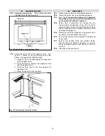
Страница 6: ...6 WITH PLINTH WITH LEGS Fig 2 Dimensions clearances ...

Страница 7: ...tal clearance to center line of meter regulator assembly located below the terminal 36 90 I Clearance to service regulator vent outlet 72 180 J Clearance to non mechanical air supply inlet to the building or the combustion air inlet to any other appliance 12 30 K Clearance to a mechanical air supply inlet 72 180 L Clearance above paved sidewalk or a paved driveway located on public property Note A...

Страница 8: ...rews for fixing base leg unit to main appliance 2 Wood screws for floor fixing 2 Plugs for floor fixing Pack 3 Vent unit contains 1 90º elbow vent 1 Vent terminal unit 1 Styrofoam support for vent tube cutting 4 6 tapping screws for vent securing 1 Length of vent sealing tape 1 Masking collar for vent joint 2 8 tapping screws for masking collar 1 Outer vent shield 7 10 nuts screws for outer vent s...

Страница 9: ...floor and over any furnishings etc in the vicinity 7 2 Mark the center of the vent hole in the wall 7 3 Cut 8 3 8 diameter vent hole through the wall making sure that it is straight and level 7 4 Place the wall plate with brackets against the inside face of the wall with the dished projection seated inside the hole in the wall and the brackets at the sides 7 5 Mark the wall plate fixing holes Remo...

Страница 10: ... allow the appliance to be disconnected for servicing 8 8 A plugged 1 8 NPT tapping must be installed in the line The tapping must be accessible for test gauge connection and be immediately upstream of the gas supply connection to the appliance 9 BASE MAIN APPLIANCE INSTALLATION 9 1 PEDESTAL BASE 9 1 1 Detach the pedestal front panel by removing two screws 9 1 2 Place the pedestal in position see ...

Страница 11: ...ure 12 Secure with 4 machine screws 9 2 9 Replace the door as follows 9 2 9 1 Locate the hinge pin at top of the door into the hole at the top of the door aperture see figure 13 9 2 9 2 Locate the hinge pin at bottom of the door into the slot in the base Swing the bottom of the door part way to the back A new door retaining bracket is supplied with the leg and facia kit Hold this bracket under the...

Страница 12: ...om the vent unit after cutting 10 10 Fit the vent terminal unit through the wall from the outside Locate the inside end fully over the elbow or horizontal extension Make sure that the seam on the outer tube is not at the bottom 10 11 Place the remaining wall plate over the outside wall end of the terminal with the dished projection facing inside Push the plate up to the wall so that the dished pro...

Страница 13: ...l for 8 tapping screws at the marked positions Make sure that the drill does not penetrate the inner duct 10 21 Place the masking collar back in position Squeeze as tight as possible and fix over the vent joint with two 8 tapping screws see figure 18 10 22 If extensions are installed seal each extra joint with tape and cover each joint with a masking collar as described in sections 10 18 through 1...

Страница 14: ...ing 12 4 All piping and connections must be tested for leaks after installation or servicing All leaks must be corrected immediately When testing for leaks Make sure that the appliance gas control knob is at the Off position Open the manual shut off valve Test for leaks by applying a liquid detergent or soap solution to all joints Bubbles forming indicate a gas leak Never use an open flame to chec...

Страница 15: ...15 ...

Страница 16: ...x sides and in the gap between each side of the firebox and the black top baffle see figure 24 15 3 Place the rear log in the retaining cradle behind the rear burner tube with its back against the back wall Center the log so that the gap to the side wall is the same at each side see figure 25 15 4 Place the centre log on the retaining cradles between the rear and front burner tubes Center the log ...

Страница 17: ...t the sides and bottom of the window frame Check ignition gas control valve and thermostat settings as described in the lighting instructions section further on in this manual 17 AERATION ADJUSTMENT As described in section 14 the burners have adjustable aeration For the great majority of installations no adjustment will be necessary However in a few instances performance may be improved by adjusti...

Страница 18: ...ance 19 3 Warn that if the ceramic window unit is damaged the appliance must be turned off immediately and not used until the window is replaced 19 4 Advise that if necessary the window may be removed when the appliance is shut off and cold to clean the inside or reset the logs if disturbed Stress that the window must be replaced securely before operating the appliance 19 5 Recommend that the appl...

Страница 19: ...ove the window unit 21 3 Open the control panel door 21 4 Insert a long burning match at the pilot 21 5 Operate the controls as described in the lighting instructions 21 6 Make sure that the pilot flame is stable 21 7 Replace the window unit securely before turning the controls to any position other than pilot 21 8 Replace the facia 21 9 Select the burner setting 21 10 Close the control panel door...

Страница 20: ... be turned to Off unless it is pushed in partially Do not force 4 Wait five 5 minutes to clear out any gas If you then smell any gas STOP Follow B in the safety information above on this label If you don t smell gas go to next step 5 Find the pilot It is at the right side of the firebox 6 Push in and turn the gas control knob counter clockwise until resistance is felt Keep pushed in at this positi...

Страница 21: ...21 Manufactured by HEATING BIRMINGHAM ENGLAND Because our policy is one of constant development and improvement details may vary slightly from those given in this publication Valor Ltd 1999 ...

Отзывы: