background image

INSTALLER’S GUIDE

Page 10

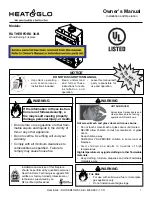
Figure 5. Flue restrictor

3     P R E - I N S T A L L A T I O N   P R E P A R A T I O N

3.1


Pack Contents

The carton contains the following:-
1    Fire unit
1    Literature Pack
1    Front coal Matrix
1    Rear coal Matrix
1    Loose coals Pack
1    Burner tray trim
3    Self-Adhesive Foam seals

2    Tension Cables
2    Cable Adjusters
1 Flue restrictor with 2 securing screws
2    Eyescrews
2    Fibre Plugs
1


Strip of Floor Sealing Tape

1    Nut and Olive for 8mm Inlet Pipe

Remove all the items carefully to prevent damage. Take special care when handling the
ceramic components. Some items may be contained in the packaging fitments - Examine
the packaging carefully before discarding.  Check that all the items are present and
undamaged.

3.2


Fireplace Flue Pull

Close all doors and windows in the room in which the appliance is to be installed. After
confirming with a match that smoke is drawn into the flue, light a 13 gram smoke pellet
and check that there is a definite flow through the flue. Verify outside that the smoke
exits from one terminal only and that the termination is suitable. Observe, where
possible, upstairs rooms and loft spaces for signs of escaping smoke indicating a
defective flue. If there is not a definite flow warm the flue for a few minutes and repeat
the smoke pellet test. If there is still no definite flow the flue may need remedial work –

Do not fit the appliance until there is a definite flow through the flue.

3.3


The Flue Restrictor

 This appliance is supplied with a flue
restrictor for use where the flue draught is
excessive. 

The restrictor must not be

fitted where a precast flue or a 125mm
flue liner is used

. For flue liners greater

than 125mm and all other installations the
restrictor should be fitted. There may
however, be certain exceptional
circumstances where fitting the restrictor
causes the fire to fail the spillage test. In such cases the restrictor will have to be
removed. After removal conduct the spillage check again.
Fit the restrictor to the appliance flue outlet as shown in figure 5 using the two screws
provided.

Содержание Harmony BR650 VA

Страница 1: ...s Installer Guide gives sufficient details to enable the appliance to be installed and maintained satisfactorily However if further information is required our Valor Technical Helpline will be pleased...

Страница 2: ...ntrol Settings 17 7 2 Check for Spillage 17 7 3 Flame Supervision Spillage Monitoring System 18 8 FINAL REVIEW 19 9 SERVICING PARTS REPLACEMENT 20 9 1 To Replace Burner Plaques 20 9 2 To Remove the Co...

Страница 3: ...d as RCF waste This is not classified as hazardous waste and may be disposed of at a tipping site licensed for the disposal of industrial waste Protective clothing is not required when handling these...

Страница 4: ...he current edition of the Building Regulations issued by the Department of the Environment and the Welsh Office In Scotland the current edition of the Building Standards Scotland Regulations issued by...

Страница 5: ...ustible material or any other combustible surface which projects beyond the front of the appliance is 100 mm at either side No side access clearance from a non combustible surface is necessary 2 7 The...

Страница 6: ...a fireback knee or other projection in the fireplace must be at least 50mm See figure 2 2 9 2 To a fireplace that has a precast concrete or clay flue block system conforming to BS1289 or BS EN 1806 Th...

Страница 7: ...ree metres restrictive terminations etc 2 9 3 A metal flue box conforming to BS715 with a minimum internal depth of 165mm Incombustible mineral wool insulation of not less than 50mm thickness must be...

Страница 8: ...ealed so that combustion products do not come into contact with combustible materials outside the chimney 2 10 4 The flue must serve only one fireplace 2 11 If the fireplace opening is an underfloor d...

Страница 9: ...placing of carpets or rugs over it The appliance must not stand on combustible materials or carpets 2 17 Propane gas appliances must not be installed in a room which is built entirely below ground le...

Страница 10: ...check that there is a definite flow through the flue Verify outside that the smoke exits from one terminal only and that the termination is suitable Observe where possible upstairs rooms and loft spa...

Страница 11: ...urner is produced from a soft ceramic material and should be handled carefully A foam seal is supplied which will need to be attached to the rear face of the firebox frame on all three sides Ensure th...

Страница 12: ...h the hole near the lower rear corner of the appliance and fit an adjuster as shown in figure 8 Repeat with the second cable at the other side With the adjusters fully screwed in carefully manoeuvre t...

Страница 13: ...the control knob back to the off position and repeat the procedure When pilot ignition has been achieved keep the control knob depressed for approximately ten seconds to allow the thermocouple probe t...

Страница 14: ...tting a pressure gauge at the test point The test point is on the pipe situated below the bottom right corner of the burner unit Check the pressure with the appliance alight and set at maximum output...

Страница 15: ...fully down See figure 10 3 Place the rear base coal in the firebox It should rest on the ledges at the sides and back of the firebox and its rear face should touch the rear ceramic wall See figure 11...

Страница 16: ...e coal of the rear base coal as shown in figure 15 9 Place the remaining type B coal at the right side of the firebox between the front and rear base coals The letter B should be upright The coal shou...

Страница 17: ...nd is due to the time required to fill the main burner compartment with sufficient gas for ignition When the burner is operating properly partially depress the knob and gradually turn it anti clockwis...

Страница 18: ...ect the appliance and advise the customer of the cause of failure 7 3 Flame Supervision Spillage Monitoring System The pilot unit incorporates a system that will automatically shut off the gas supply...

Страница 19: ...appliance will operate to its maximum potential if the flue is primed during the first 20 30 minutes of use To do this simply turn the control to its highest setting This will also burn off any carbon...

Страница 20: ...d as hazardous waste and may be disposed of at a tipping site licensed for the disposal of industrial waste Protective clothing is not required when handling these articles but we recommend you follow...

Страница 21: ...nd disconnect the appliance from the elbow Detach the burner unit from the hotbox by removing 1 screw As shown in figure 6 Replace in the reverse order 9 3 To Remove the Pilot Unit Remove the complete...

Страница 22: ...Particularly make sure that the gas ports in the tap are not restricted by grease Push the plug into the tap body and position the slot in line with the mark previously made on the tap body Reassembl...

Страница 23: ...70 For Propane Appliances 1 0581199 B Gas tap spark generator 1 0569429 C Spark generator 1 0521069 D Control knob 1 0545979 E Pilot unit For Natural Gas Appliances 0540979 Pilot unit For Propane Appl...

Отзывы: