background image

3

© Vallox Oy - All rights reserved

USING THE UNIT

The fan speed of the Vallox ventilation unit is adjusted 

using a four-step control.
The available speed options of the control switch  

are 1, 2, 3, and 4:
1.  

Away mode. The ventilation efficiency can be 

temporarily reduced when the apartment is 

unoccupied.

2-3.   Standard mode. In standard mode, the air inside the 

apartment is replaced once every two hours. 

4.  

Boost mode. Cooking, sauna, bathing, drying of 

clothes, guests, and other similar situations can 

require that ventilation be increased from the 

standard setting.

The fan speed can also be controlled through a separate 

Vallox control hood, the Vallox ProControl panel, or 

directly through voltage messages (0-10 V).

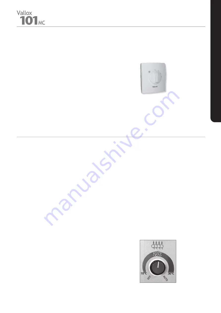
Vallox Simple Control panel

The temperature of the air blown into the apartment can 

be adjusted approximately b10 °C and +30 °C.  

The unit has an automatic summer/winter function  

(a bypass flap).

•  When the adjusted temperature is b10 °C 

and +30 °C, the heat recovery cell is not bypassed, 

i.e. the unit is in winter mode.

•  In the OFF position, the unit is in the summer mode, 

i.e. post-heating is turned off and the heat recovery 

cell is bypassed when the outdoor temperature is 

above +14 °C. The heat recovery will be turned on 

when the outdoor temperature falls below +12 °C.

•  In the AUTO position, the unit will operate as follows 

around the year: The default post-heating setting 

is +17 °C. The unit will bypass the heat recovery cell 

when the temperature of the outdoor air exceeds 

+14 °C. The heat recovery will be turned on when the 

outdoor temperature falls below +12 °C. During the 

bypass, post-heating is turned off.

Adjusting supply air temperature

FAN SPEED ADJUSTMENT

ADJUSTING THE SUPPLY AIR TEMPERATURE  

AND SUMMER/WINTER FUNCTION

The winter function of  

the ventilation unit

The limit value has been set in the factory for freezing of 

the heat recovery cell. When this limit value is exceeded, 

the ventilation unit starts to defrost the heat recovery cell 

by directing the outdoor air past the heat recovery cell.
The duration of the defrost cycle is 15-45 min depending 

on the amount of ice accumulated in the heat recovery cell 

and on the extract air flow. The factory settings ensure 

optimal operation in standard living and detached house 

conditions. Even though the winter operation parameters 

can be adjusted for certain extreme conditions, such as 

swimming pool facilities, it is always advisable to contact 

Vallox maintenance services.

Содержание 101 MC R

Страница 1: ...Manual MANUAL Ventilation unit Document D4686 Valid from 02 05 2022 Updated 16 05 2022 Model Vallox 101 MC R Vallox 101 MC L Type C3740 ...

Страница 2: ...ack of knowledge and experience do not ensure safe operation of the unit Such persons can use the unit under supervision or by following the instructions of someone who is responsible for their safety 12 13 14 Vallox Simple Control panel ordered separately Vallox ProControl panel ordered separately 15 Ceiling bushing for electric wires Vallox Delico PTD EC optional 14 optional 13 optional 12 Vallo...

Страница 3: ...at recovery cell is bypassed when the outdoor temperature is above 14 C The heat recovery will be turned on when the outdoor temperature falls below 12 C In the AUTO position the unit will operate as follows around the year The default post heating setting is 17 C The unit will bypass the heat recovery cell when the temperature of the outdoor air exceeds 14 C The heat recovery will be turned on wh...

Страница 4: ...f the outdoor air is faulty Check the sensor and the wires replace as required 6 The supply air fan has stopped Check the wiring of the fan replace the fan as required 7 The extract air fan has stopped Check the wiring of the fan replace the fan as required 8 EEPROM is faulty Replace the circuit board Concealed installation of the fireplace switch optional TROUBLESHOOTING TABLE If the ventilation ...

Страница 5: ...s on the ambient dust concentration It is recommended that the filters be replaced every spring and autumn or at the very least once a year HEAT RECOVERY CELL Check that the heat recovery cell D is clean roughly once a year when the filters are being replaced Clean by washing as required Remove the sealing strip E above the heat recovery cell in the direction of the arrow Also remove the extract a...

Страница 6: ...recovery cell 5 Disconnect the quick connector H of the supply air fan T and or the extract air fan P cables 6 Push the fan cables and the rubber feed through I into the fan chamber 7 Remove the screws used to fasten the fans J 3 screws per fan Undo the mounting screws K 3 screws per fan of the air flow control grille of the fan and remove the grille S 8 Remove the fan from the unit by pulling it ...

Страница 7: ...e heating season begins e g during autumn maintenance check that the condensing water outlets in the bottom pool are not clogged To check this pour some water into the pool Clean as required Water must at all times be kept out of the electrical system See the condensing water connections on page 15 291 291 147 5 147 5 R model L model Installation of the Vallox Silent Klick siphon on the bottom poo...

Страница 8: ...al resistor 1500 W Pre heating Additional heating Fans Supply air Extract air 0 115 kW 0 95 A EC 0 115 kW 0 95 A EC Specific energy consumption SEC in a cold climate in a temperate climate A A Operating efficiencies Annual efficiency Supply air efficiency Specific Fan Power SFP 75 82 1 33 kW m3 h 63 dm3 s Filters Supply air Extract air ISO Coarse 75 ISO ePM ISO Coarse 75 Heat recovery bypass Autom...

Страница 9: ...1 74 78 83 85 88 88 54 57 63 66 70 75 78 79 80 LWA dB A 43 53 57 61 65 68 71 72 74 35 40 45 49 53 55 58 59 60 Sound pressure level coming through the envelope of the unit in the room in which it is installed 10m sound absorption Adjustment position Air flows supply extract Adjustment position V 3 1 4 1 5 2 6 2 7 3 8 1 9 2 10 2 11 4 Air flow dm s 15 20 24 30 33 40 42 48 52 58 61 68 70 76 78 84 83 8...

Страница 10: ...link between connectors 3 and 5 from the female side of the control panel connector Post heating control PWM level adjustment 4 5 6 Protective earth to a separate block 7 8 9 1 Supply air fan 2 3 Extract air fan 4 5 LINE NEUTRAL SLI SNI SLO SNO SFL Extract air NTC Outdoor air NTC Supply air to the apartment NTC Exhaust air NTC Supply air from the cell NTC SFN EFL EFN FSO FSI AHL AHN PHL PHN 230V 5...

Страница 11: ...ector GND S GND S MC VENTILATION UNIT Four terminal connector MV VENTILATION UNIT GND AN I RM I RM O E I LED E O PROGRAMMING CONNECTORS OF THE MOTHERBOARD CONTACT DATA GUARD FUNCTION NORMAL SITUATION OPEN ACTIVATED CLOSED HOUSE AUTOMATION NORMAL SITUATION OPEN ERROR SITUATION HOOD OR VENTILATION UNIT CLOSED ACTIVATED GUARD FUNCTION FLASHING POSITION OF THE DAMPER DAMPER CLOSED CONTACT OPEN DAMPER ...

Страница 12: ...485 Common RH optional 946147 Nomak 2x2x0 5 0 5 0 10V LED G G0 Y1 Y2 DI1 A1 Y3 A2 Y4 U1 A B C S DI2 G0 Vallox Procontrol 949034 S LED S B term CONFIG Control signal S Cooker hood or boost switch 11 2 VDC GND DISTRIBUTION BOARD L N 24V Error relay LED Nomak 2x2x0 5 0 5 Modbus RS 485 Nomak 2x2x0 5 0 5 Cable types specified in the drawing are indicative 2x0 5 2x0 5 Internal connection of the ventilat...

Страница 13: ...ll mounting plate The top surface of the side panel of the unit can be installed against the finished ceiling surface When the wall mounting plate is used it must be observed that the ventilation unit will rise roughly 10mm above the final installation height The outer diameter of the duct is 12mm Mounting on the wall NOTE Avoid mounting the unit on a hollow echoing partition wall or on a bedroom ...

Страница 14: ...ing plate Installing the ventilation unit to the ceiling mounting plate Remove the unit door Lift the unit and take the wires through the opening in the ceiling mounting plate Lift the ventilation unit against the ceiling mounting plate so that it locks in place The unit has become locked on the ceiling mounting plate when the two operating levers on the mounting plate have been restored to the sa...

Страница 15: ... siphon Installation height 53 mm installation space 73 mm outer diameter of the duct 12 mm Location of the condensing water outlets R and L models If the Vallox Silent Klick siphon does not fit into the unit directly the elbow can be installed at the bottom and the siphon can be installed on the wall This installation method requires that there is a 47 mm space underneath the unit The elbow requi...

Страница 16: ...4102504 8 Upper support for HR cell 3467200 9 Filter frame extraction 978226 10 Coarse filter for extract air 978227 NO Part Product number 11 HR cell bypass damper assembly 4102523 12 Damper motor 930621 13 Post heating resistor 942220 14 Door 4102334 15 Mounting screw of the door 990712 16 Motherboard 949035 17 Safety switch 948370 18 Glass tube fuse 320 mA slow 5x20 mm 952486 19 NTC sensor spec...

Отзывы: