A V I O N I C S L I M I T E D
2.3.3 NAV/GLIDESLOPE/MARKER ANTENNA INSTALLATION
Navigation, Glideslope and Marker antennae should be installed as
per FAA Advisory Circular AC43.13-2A Methods and Guidelines and
the appropriate manufacturers instructions.
Navigation couplers can be utilized to provide multiple system
operation from one navigation antenna.
2.3.4 AUDIO
INTERFACE
Audio output for the
INS 422
is rated at 10 MV into a 600 Ohm load.
Therefore, proper amplification will depend on using either an
auxiliary input of existing communications transceivers or connection
to an amplified audio panel. This will insure a sufficient level of
amplification.
2.3.5
THE HARNESS ASSEMBLY AND INSTALLATION HARDWARE
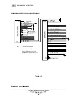
Val Avionics, Ltd supplies the harness assembly and three BNC
connectors required. The
INS 422
will require that a 5-amp circuit
breaker or fuse be used for circuit protection. The wire functions and
color-codes for P1205 are specified in Figure 1.3 Page 22.
The "Automatic Radial Centering" feature can be accessed and
operated when the remote momentary pushbutton switch (VPN
501117) is installed. Refer to Figure 1.4 on Page 23. When the
"Automatic Radial Centering" momentary switch is installed, it must
be installed in the immediate vicinity of the INS 422 unit. This switch
must be placarded appropriately as to its function.
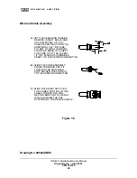
2.3.5.1 BNC
CONNECTOR
For termination instruction of the BNC Connector on RG58 type
coaxial cable for connection to the aircraft NAV/GLIDESLOPE and
MARKER antenna and/or coupler, refer to Figure 1.6 on Page 25.
INS 422 Installation/Owners Manual
Original Issue – June 2001
VPN 701034
12


