


A V I O N I C S L I M I T E D
2.3.2.1 PANEL
LOCATION
The
INS 422
is rigidly mounted in a standard 3.125” round cutout on
the aircraft panel. Once a location has been selected, a visual
inspection should be made of the area directly behind the panel
which, will be occupied by the
INS 422
and harness assembly for
obvious obstructions such as heater ducts, control cables, fuel and
oil lines or any other obstruction.
Pay particular attention to the control yoke assembly. It should be
moved to the full limit of travel and verified that sufficient clearance
exists prior to beginning installation.
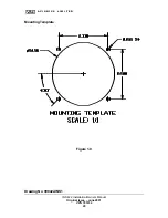
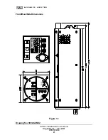
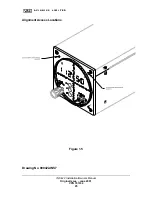
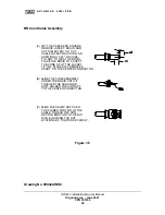
2.3.2.2 MOUNTING
Most aircraft instrument panels will already have existing instrument
mounting cutouts. If the location you have selected requires that a
mounting hold be cut, refer to Figure 1.0 on Page 19 for the
mounting template. Mark and cut the mounting holes as required.
Position the unit in its upright position, and from the rear of the panel,
place the unit into the selected 3.125” panel cutout. With the unit
held in place, insert four of the supplied 6-32 X 3/8” screws from the
front and tighten as appropriate. The installing agency must
fabricate and attach rear support brackets to the aircraft structure
behind instrument panel as appropriate to support the rear of the
INS
422.
Then, attach these brackets to the provided attachment points
on the rear of the unit with the supplied 6-32 3/8" Screws and 6-32
Fibernuts.
To remove unit, reverse the above procedure.
INS 422 Installation/Owners Manual
Original Issue – June 2001
VPN 701034
11