4 Set-up
24
Installation and maintenance instructions 0020237953_00
4 Set-up
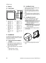
4.1 Dimensions
A
F
Ø E
B
C
D
A
VAE 90/1 AHT:
170 mm
VAE 150/1 AHT:
190 mm
B
VAE 90/1 AHT:
170 mm
VAE 150/1 AHT:
190 mm
C
VAE 90/1 AHT:
53 mm
VAE 150/1 AHT:
53 mm
D
VAE 90/1 AHT:
38 mm
VAE 150/1 AHT:
43 mm
E
VAE 90/1 AHT:
100 mm
VAE 150/1 AHT:
120 mm
F
VAE 90/1 AHT:
7 mm
VAE 150/1 AHT:
7 mm
5 Installation
To install and operate the product, an ex-
isting room ventilation system or outdoor-
air opening is required.
5.1 Determining the installation
location
1. When determining the installation loc-
ation, take into consideration the pro-
duct's sound power level.
2. Take the pipe diameter into considera-
tion.
–
VAE 90/1 AHT: 100 mm
–
VAE 150/1 AHT: 120 mm
5.2 Installing the pipe
1. Insert a pipe into the designated posi-
tion on the wall on site.
2. Note that the pipe must be installed
with a downward gradient to the out-
side.
3. Ensure that the power supply cable is
not damaged when drilling through the
wall.
5.3 Installing the fan unit
1. Take into consideration the correct
routing of the power supply cable.
Conditions
: Automatic mode
–
A two-core cable is required for
automatic operation.
Conditions
: Manual mode
–
A three-core cable is required for
manual operation.
2. Ensure that the power supply cable is
not damaged.
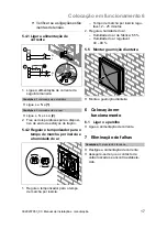
3. Remove the front panel from the fan
unit.

