


Standard Accessories
Art. No.
1. Air/flue duct and terminal accessory
300 807
Optional Accessories
Art. No.
1. Vertical air / flue duct (including terminal)
300 800
2. Pitched roof adjustable roof tile
(for use with vertical air/flue duct)
9076
3. Flat roof penetration collar
(for use with vertical air/flue duct)
9056
4. 1 m air /flue duct extension
300 802
5. 2 m air / flue duct exension
300 803
6. Additional 90° elbow for air / flue duct
300 808
7. Additional 45° bends (pair) for air / flue duct
300 809
8. Additional air / flue duct joint clamps (pair)
300 806
9. Se- duct flue kit
300 810
10. Internal flue fixing kit
8098
11. Pre - installation connecting group
(includes 300 813)
8015
12. Vaillant boiler replacement connection accessory
300 813
13. Pipe cover accessory
8099
14. Plug in 24 hour central heating timeclock
300 820
15. Plug in 7 day central heating timeclock
300 821
14
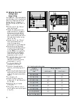
4.2.1 Installation accessories
Table 3 lists the standard and optional
accessories which are available for
the TURBOmax combination boilers.
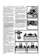
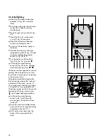
4.2.2 Unpack the boiler (fig. 11)
Open the boiler carton and remove:
a. protective cardboard sheet
b. top and bottom decorative panels
c. polystyrene packaging
Note: Care should be taken not to
scratch the white surface of the boiler
casing.
Packed in the boiler carton are the
following:
•
boiler installation template
•
boiler hanging bracket
•
gas service valve
•
fixing screws and wallplugs
•
installation and user instructions
•
flue restrictor
•
domestic hot and cold water
connections and straddle bracket
4.3 Preparation of boiler
location
4.3.1 Select position of boiler.
Refer to Section 3.2 'Boiler Location'
for information regarding siting the
boiler. In general the boiler must be
positioned such that:
•
there is adequate space around the
boiler for service and maintenance
•
the boiler can be correctly flued,
i.e. the flue terminal position is sited
in accordance with Section 3.4.1
and the air / flue duct can be
installed in accordance with the
flue installation instructions
supplied.
•
all necessary pipework can be
connected, including the pressure
relief valve discharge pipe.
fig. 11
GW 601/1
Table 3: Installation Accessories


