35
7.4 Replacement of burner
•
Isolate the boiler from the electrical
supply.
•
Remove front casing as in section
7.1.3.
•
Remove combustion chamber cover
as in section 7.1.5
•
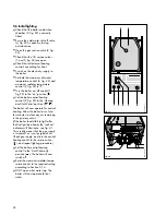
Disconnect the ignition and flame
sensing electrode leads (1, fig. 57).
•
Remove two screws (2, fig 57) and
pull burner forwards to remove.
•
Reassemble in reverse order.
•
Carry out electrical checks (see
section 5.1) and check burner
pressure (see section 5.8) and gas
rate.
7.5 Replacement of electrodes
•
Isolate the boiler from the electrical
supply.
•
Remove front casing as in section
7.1.3, and remove combustion
chamber cover as in section 7.1.5
•
Remove heat exchanger front panel
as in section 7.1.7
•
Pull off HT lead (ignition electrode)
or sensing wire (flame sensing
electrode) (1, fig 57)
•
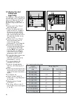
Depress spring retaining clip (1, fig
58) gently pull electrode up and
clear of burner.
•
To replace the electrode, depress
spring retaining clip (1, fig 58) and
insert electrode until the "V" locates
in the cross support (2, fig 58)
•
Carry out electrical checks (see
section 5.1).
5
4
2
3
1
6
fig. 57
GW 641/1
2
1
fig. 58
GW 642/1


