


35
Installation and maintenance instructions ecoTEC plus 0020031552_03
5.10
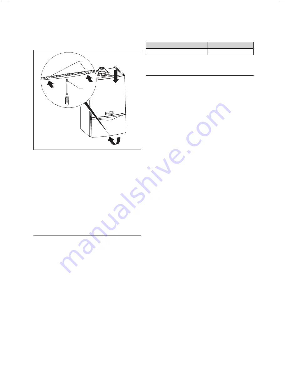
Fitting the front casing
1
2
Fig. 5.7 Fitting the front casing
• Hook the front casing section into the tabs at the top
of the frame of the combi boiler and slide the lower
section of the casing into the position provided.
• Make sure that the spring clips (
2
) engage properly.
• Tighten the securing screw of the enclosure (
1
).
5.11
Setting the output of the central heating
(range rating)
The appliance is fully modulating for central heating and
it is therefore not necessary to range rate the appli-
ance. However if desired it is possible to range rate the
boiler as follows:
• Press the "
i
“ and "
+
“ buttons simultaneously.
• Hold the button "
+
“ down until "
d.0
“ is displayed.
h
Note
The display runs from "d.0“ to "d.99“ and then
starts again at "d.0“.
• Press the "
i
" button.
The symbol "
=
“ is displayed. Then the part load setting
is shown in kW.
• Use the buttons "
+
“ and "
–
“, to increase or decrease
the displayed value in steps of 1 kW. The displayed
value flashes during the setting process. The available
setting ranges are shown in Table 5.2.
• Push the button "
i
“ for about five seconds or until the
display stops flashing. This stores the value in the
memory. The display reverts back to the normal sta-
tus (display of current feed temperature, for example
45 °C).
• To de-activate the setting mode, simultaneously push
the buttons "
i
“ and "
+
“.
The setting mode is also de-activated if a button is not
pushed within a period of 4 minutes.
Appliance
Heating output in kW
ecoTEC plus 937
12 - 28
Table 5.2 Setting the part load ranges of the heating system
5.12 Gas
conversion
h
Note
To convert the appliance from natural gas to
liquid gas you will need the Vaillant modification
kit Part No. 00 2001 0641.
To convert the appliance from liquid gas to natural
gas you will need the Vaillant modification kit
Part No. 00 2001 0642.
Perform the conversion of the appliance in
accordance with the description in the modi-
fication set.
Commissioning, Part I 5
Содержание ecoTEC plus 937
Страница 60: ......
Страница 61: ......
Страница 62: ......
Страница 63: ......
Страница 64: ...0020031552_03 GB 052008...