VAG Operating and Maintenance Instructions • 4
4.2 Installation location
The installation location of the valve must provide enough space
for operation, later function tests and maintenance works (e.g. re-
adjusting the lateral seal). If the valve is to be installed outside, it
has to be protected by adequate covering against direct weather
influences such as icing. If the valve is mounted as an overflow
installation, higher operation forces and higher wear and tear of
the relatively moving parts must be expected. This fact is to be
taken into account when determining the maintenance intervals
If the valve is to be installed at pipeline end, make sure that the
free outlet is absolutely inaccessible for anybody.
Warning!! The nominal pressure on the closed valve must not be
exceeded (see document KAT 2410-A). In case of a pressure test
in the pipeline using higher pressures than the admissible nomi-
nal pressure, close the gate valve with a cover and slightly open
the knife during the test.
4.3 Installation position
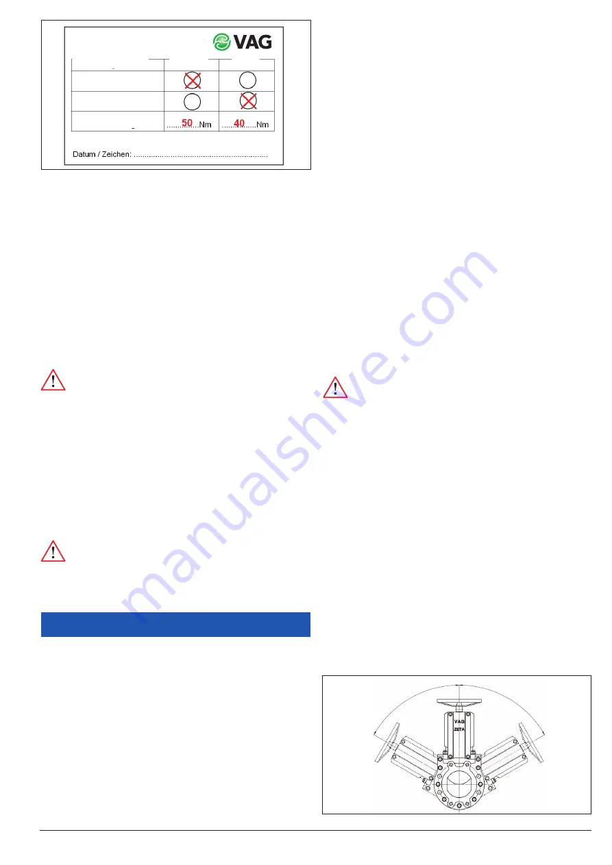
If the valve is to be installed in a horizontal pipeline and if the
media conveyed contain solid particles (e.g. sand, etc.), the valve
should not be inclined more than 60° from the vertical position
(see Fig. 2). This allows the continuous flushing of the operating
area and reliable guiding of the knife.
In different installation positions, especially if the valve is sus-
pended or installed horizontally in a vertical pipeline, increased
deposition of solids on the knife cannot be avoided. This increa-
ses the risk of malfunction (e.g. wear of the lateral seal, increa- sed
operating forces, etc.) and requires more frequent maintenance.
Attention:
To ensure its proper function at all times, the
valve should not be installed outside the permissible range.
In case of deviating installation positions, always contact
the manufacturer for technical coordination, providing pre-
cise information about the installation position, operating
conditions and quality of the medium (especially about its
solids content).
If assembly and maintenance work are carried
out on valves with a suspended installation positi-
on, the knife must be secured on site against fal-
ling out when the lateral seal is being replaced.
Attention! Exception!
VAG ZETA
®
control valve with VAG control orifice. The ZETA
®
control
valve must be installed in a vertical position as otherwise its func-
tion may be affected by the accumulation of dirt upstream of the
control orifice.
Concerning the installation direction of the ZETA
®
control valve,
the following instructions must be observed:
• The control orifice must be positioned in flow direction
downstream of the knife!
• The control orifice must be positioned in pressure direction
(direction of action of the differential pressure after closing)
downstream of the knife!
3.2 Applications
In its standard version, the VAG ZETA
®
Knife Gate Valve with NBR
sealing material can be used for the following media:
• Water, raw water, cooling water, municipal waste water,
grease- and oil-containing media, weak acids and bases
For alternative operating conditions and applications, please con-
tact the manufacturer.
3.3 Permissible and impermissible modes of
operation
Avoid the exertion of excessive force caused by using ex-
tensions on the operating elements, as this may dama- ge
the valve due to overload.
The ZETA
®
Knife Gate Valve with electric multiturn actuator
is suitable for „Open/Close“ operation. For special control
applications, special versions such as the ZETA
®
control
with control orifice are required.
The maximum operating temperatures and operating pressures
specified in the technical documentation must not be exceeded.
The closed knife gate valve must not be exposed to pressures ex-
ceeding its nominal pressure (see Table 3 / nominal pressure PN).
Upon delivery, the tight sealing of the valve is only guaran- teed
up to its maximum permissible operating pressure.
The valve has been designed for operation in liquids. If it
is operated temporarily in dry media, increased operating
forces as well as increased wear of the lateral seal and the
U-profile seal are to be expected. Permanent dry operation
is impermissible for technical reasons!
4 Installation into the pipeline
4.1 Conditions required on site
When installing the valve between two pipeline flanges, these must
be coplanar and in alignment. If the pipes are not in align- ment,
they must be aligned before installation of the valve, as otherwise
this may result in impermissibly high loads acting onto the valve
body during operation and eventually even lead to fracture.
The valve is to be installed tensionless into the pipeline. No pipe-
line forces must be transmitted from the pipeline onto the valve.
The space between the flanges should be wide enough to prevent
damage to the coating of the flange gasket frames during instal-
lation.
In case of works around the valve causing dirt (e.g. painting, ma-
sonry or working with concrete), the valve must be protected by
adequate covering.
Picture 1: Example of a label showing the adjustments of the electric actuator
Factory-adjusted drive!!!!
Unauthorised changes result in
the loss of warranty
Position dependent
Torque-dependent
Torque adjusted
Control
Open
Closer
60 °
60 °
Picture 2: Installation position of the VAG ZETA
®
Gate Valve


