VAG Operation and Maintenance Instructions • 14
In case the operator’s employees do not have the qualifications
required, they need to attend a training course. This training
course can e.g. be held by VAG Service employees.
In addition to this, the plant operator needs to ensure that all
employees have understood these Operation and Maintenance
Instructions as well as all further instructions referred to in them.
Protective equipment such as safety boots, safety helmets, gogg-
les, protective gloves etc. must be worn during all work requiring
such protective equipment or for which such protective equip-
ment is prescribed.
Improper or wrong use of the valve should be avoided. Prior to
the performance of any work on the valve and equipment it must
be ensured that the relevant pipeline section has been depressu-
rised and/or de-energised.
7.2 Inspection and operation intervals
The valve should be checked for tightness, proper operation and
corrosion protection “at least once per year” (DVGW Instruction
Sheet W 392).
In case of extreme operating conditions inspection should be per-
formed more frequently.
7.3 Maintenance work and replacement of
parts
7.3.1 Design
The design view in Picture 12 serves as a partial overview for the
descriptions of the working steps below. For information about
spare parts and their part numbers, please refer to the document
VAG KAT 1310-E.
7.3.2
Recommendations for the replace-
ment of parts
Profile seals and O-rings must be replaced whenever necessary.
The replacement intervals depend on the operating conditions.
7.3.3 Cleaning and lubrication
When being replaced, the profile seal and the O-rings should al-
ways be lightly greased. Use lubricants with approval for applica-
tion with foodstuffs or drinking water.
Recommended lubricants:
• For the profile seal and the O-rings: KLÜBERSYNTH VR 69-252
(with KTW approval for drinking water) Manufacturer: Klüber
Lubrication München AG, Germany.
7.3.4 Replacement of the profile seal
Due to the double-eccentric bearing, the profile seal can be re-
placed without disassembly of the disk. Valves of up to DN 1000
must either be completely dismantled from the pipeline or at least
disconnected from the pipeline on one side to replace the profile
seal. In the same way as for the installation of the disk, all safety
precautions need to be taken.
Disassembly of the sealing ring:
• Open the disk (2) until the profile seal (3) emerges from the body
• Unfasten the retaining ring screws (5.1)
• Remove retaining ring (1) and sealing ring (3)
• Clean the disk (2) in the sealing zone
• Check the seat ring in the body for damage or deposits
• Insert the new sealing ring into the groove of the disk and slight-
ly grease it with KLÜBERSYNTH VR 69-252
• Insert the hexagonal screws (5.1) and fasten them using the
torque specified in Table 1 (Section 7.3.6 Tightening torques
for screws)
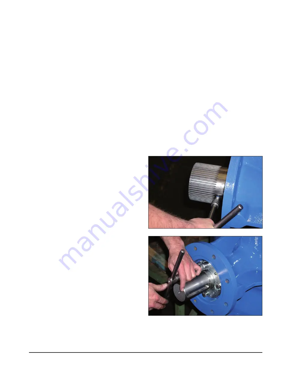
7.3.5 Replacement of the O-rings in the
bearing
For this kind of maintenance work, the valve must be depressu-
rised.
• Turn the butterfly valve (2) into closed position
• Unfasten the hexagonal nuts at the gear flange and pull the
gear off the shaft (7)
• Loosen the threaded pin and pull off the coupling. Pull the ad-
justment spring (20) off the shaft
• In the depressurised pipeline, the hexagonal screws (14) are
unfastened and the bearing flange (10) as well as the bearing
cover (11) are pulled off. Slightly grease the O-rings (17 / 16)
with KLÜBERSYNTH VR 69-252 before installation.
Picture 17: Replacement of O-ring - Step 1
Picture 18: Replacement of O-ring - Step 2
• Reassembly is done in reverse order
• Tighten the hexagonal screws (14) only slightly to prevent ten-
sioning the bearing bush (12) on the disk (2). Secure the flange
position using the threaded pins (15).


