background image


16   


Ø


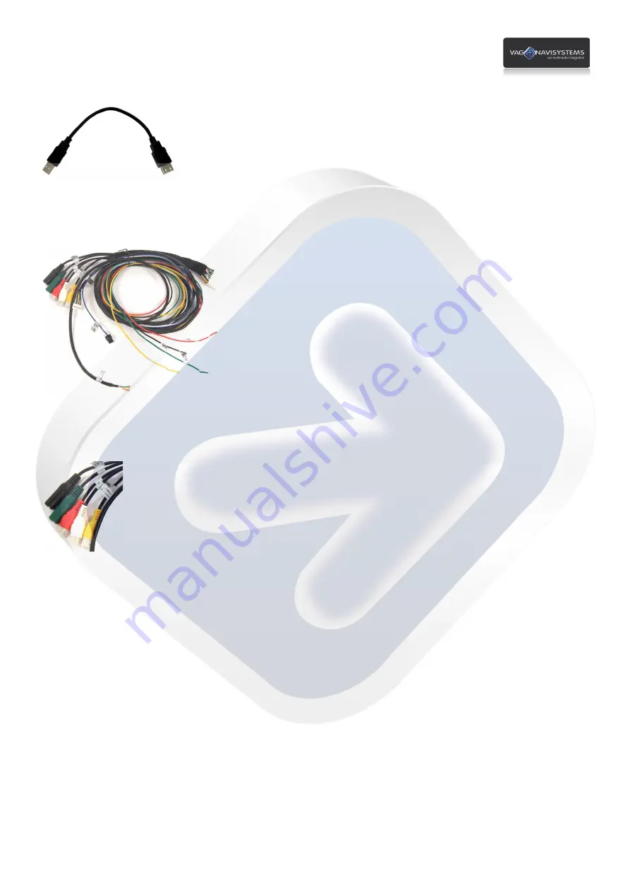
USB   extension   cable:   


Connect   to   the   USB   port   interface   GPS   Box   of   the      

Ø


GPS   Box   POWER   cable:   


Connect   to   the   interface   GPS   Box   

POWER   &   DATA   

port   interface   GPS   Box   

Ø


RCA   and   Jack   connectors:   


White

   Conector:   

AUDIO   L   OUT,   

connect


to   the   left   side   audio   IN   of

   the   voice   module      


Red

   Conector:   

AUDIO   R   OUT,   

connect


to   the   right   side   audio   IN   of

   the   voice   module   


Green

   Conector:   

Green


MIC,   

jack


3.5mm   connection   for   microphone   

(if   it’s   going   to   be   used)   


Yellow   

Conector:

   VIDEO   OUT,

   GPS   Box   video   out   connection   

(if   RGB   OUT   is   not   being   used)   


Black

   Conector:   

IR,

   No   function   


GPS   Box   must   be   accessible   to   be   able   to   connect   the   SD   card,   the   placement   on   the   auto   glove   
compartment   it’s   ok,   holded   by   double   face   tape   or   with   plastic   flanges,   will   be   enough,   you   also   have   to   
make   a   hole   (diameter   of   about   20mm)   on   the   back   of   the   glove   compartment   to   pass   the   GPS   Box   cables   
through   it.   


Содержание NaviTouch A6-Q7

Страница 1: ... Installation and configuration manual Compatibility with vehicles which have MMI 3G radio LOW II and a 6 5 color display ...

Страница 2: ... 2 3 5 Sound integration wiring harness Page 12 2 4 POWER connector cables and connections Page 13 2 5 Aftermarket rear camera connection Page 14 2 6 GPS Box installation and connections Page 15 2 7 Voice module installation and connections Page 18 2 8 Linking up the interface GPS Box and the multimedia interface Page 19 3 GPS Box Configuration System Configuration Page 20 3 1 Calibrating touch an...

Страница 3: ...duct losses his warranty if you dismantle it or if you try to fix it without the manufacturer permission If you break up product security stickers warranty will be lost too Check that you have received all the product components before the installation If you see any part damaged or faulty contact us immediately Problems made by a user mistake in the installation or manipulation of the product sup...

Страница 4: ...mponents 1ea 1 unity Multimedia interface Additional module SUB BOARD IR cable 4P 1ea MODE cable 1ea POWER cable 24P 1ea AV cable 1ea TOUCH OUT cable 1ea REAR CAMERA POWER cable 1ea LVDS cable 1ea TOUCH cable 1ea Remote Control 1ea Original LCD cable HSD 1ea ...

Страница 5: ...e components GPS Box Touch screen GPS Box POWER cable GPS antenna Hidden microphone Specific for overhead courtesy lights panel Speaker Optional installation USB extension cable Voice module Voice module Quadlock cable Voice module audio cable ...

Страница 6: ... SUB BOARD Ø Navigation GPS Box Ø Touch cable Ø LVDS cable Ø Original LCD cable HSD Ø Offered Touch cable Ø Monitor Ø Touch Screen Ø Head unit Ø Original LCD cable Ø CAM Ø RCA Ø POWER Ø GPIO ZO MMI NOTE The not identified connections in this diagram or the useless ones must be isolated ignorated ...

Страница 7: ...ween sources Dip 1 is used for navigation source RGB connection See the next sample image VERY IMPORTANT DIP Switch UP Enable DIP Switch DOWN Disable Ignore ON inscription Like this in the sample image DIP 1 up Enabled DIP 2 down Disabled DIP 3 down Disabled DIP 4 up Enabled DIP 5 up Enabled DIP 6 up Enabled DIP 7 down Disabled DIP 8 up Enabled DIP Switches function DIP 1 Enable disable RGB GPS Bo...

Страница 8: ...mpartment Disconnect the electric connector of the auto glove box compartment and remove the auto glove box compartment Once you have removed it you will have enough space to perform the connections between the multimedia interface the additional module and the vehicle s screen and you will have too space to place the multimedia interface It will be necessary to remove the aerator from the center ...

Страница 9: ...mbling it follow the steps Move the steering wheel down as far as possible Push the cover trim 1 in the buttons unit of the dashboard following the arrow s direction Remove the cover trim 1 and separate it from the switcher Place the 3438 hook in the hole extract the buttons kit and disconnect it See it on the image below ...

Страница 10: ...w Place the 3438 hook in the hole watch the arrow in the buttons unit extract the buttons kit and disconnect it Now will be necessary to remove the cover trim located between the MFD and the steering wheel separate it by the lower ends and remove it Then unscrew the screws of the MFD cover trim ...

Страница 11: ...ouch panel First we will have to disassemble the screen s metal frame by using a nylon wedge and a flat screwdriver to pry Now remove the screen s metal frame and clean the screen using a specific cleaning product and a microfiber cloth Then we will place the touch screen and the screen s metal frame NOTE Don t tighten too much the metal frame it only has to be holded ...

Страница 12: ...UB BOARD module and the HSD connection behind of the radio Disconnect the Purple Original LCD cable HSD of the radio and connect it to the SUB BOARD module TO MONITOR connection port The TO SYS cable must be connected to the connector that we leaved free previously see it on the image Then connect the LVDS cable 1ea to the FROM I F connection port of the additional module SUB BOARD and connect the...

Страница 13: ...module located at the right side of the trunk Disassemble the charge shelf and the tool compartment box as shown on the image The radio module is located at the right side of the trunk see the images below The voice module audio cable must go from audio OUT of the Navitouch to voice module located at the right side of the trunk too ...

Страница 14: ...cle hand break you will stop seeing the interface images Security mode TV FREE OFF IR NAVI No function IR AV1 DVD Connection cable to the IR control cable from the multimedia device connected to the RCA AV1 entry of the multimedia interface to enable his own controls using the touch screen optional IR AV2 DMB Connection cable to the IR control cable of the multimedia device connected to the RCA AV...

Страница 15: ...rom the rear light the CAM connector won t supply power to the camera so the camera won t work Don t forget to adjust the DIP Switch 7 of the multimedia interface once all connections have been done DIP Switch 7 Enable disable aftermarket rear camera or OEM DIP Switch 7 Up enable OEM camera without aftermarket rear camera DIP Switch 7 Down enable the aftermarket camera The rear gear signal mustn t...

Страница 16: ...D light that indicates if GPS Box is working CA No function SD SD card connection port Maps Multimedia Ø GPS antenna NOTE Place preferably the antenna on the dark zone of the car s front glass it will be necessary to disassemble one of the A pilar trims Connect to the GPS antenna port of the interface GPS Box Ø Hidden microphone specific for locate at overhead courtesy lights panel Connect to the ...

Страница 17: ...IN of the voice module Green Conector Green MIC jack 3 5mm connection for microphone if it s going to be used Yellow Conector VIDEO OUT GPS Box video out connection if RGB OUT is not being used Black Conector IR No function GPS Box must be accessible to be able to connect the SD card the placement on the auto glove compartment it s ok holded by double face tape or with plastic flanges will be enou...

Страница 18: ...ection from the GPS Box TOUCH SCREEN cable to the multimedia interface Touch cable TOUCH OUT cable 1ea Ø POWER cables speaker and mute NOTE The POWER connection always must be the last step in installation Black cable GND connect to the vehicle s mass you must weld don t braid Red cable ACC connect on 12V ACC ignition Yellow cable BATT connect on 12V ACC ignition White blue cable SPEAKER Speaker c...

Страница 19: ...iring harness red to red white to white Ø Voice module Quadlock Plug and Play harness Connect the female Quadlock connector of the Voice module Quadlock Plug and Play harness to the male Quadlock connector of the rear radio module at the trunk once you have removed vehicle s radio module located at the right side of the trunk connect the Voice module Quadlock Plug and Play harness male connector t...

Страница 20: ...n connect all the power cables of the different component and devices that will be used always with the vehicle stopped and with the ignition key out of its port then connect again the connectors that you had removed from the radio and place the radio on its original position start the vehicle to check if radio works properly Then we are going to proceed to configure the system for its tune up Tec...

Страница 21: ...s until you receive OK message at this way you will have calibrated successfully the touch screen gps function if it doesn t appears OK message you must repeat this process again Once you have done the calibration process it will appear this message Unable to find navigation software push on this message to omit it Then you must config the multimedia interface push the Menu button of the multimedi...

Страница 22: ...UCCES this way you will have calibrated successfully the touch screen if while you are doing the calibration process appears the message FAIL you must repeat the process again Doing this you will have configured the interface to be able to change the mode by touching on the AV1 AV2 and AV3 inputs Now you will have to adjust the screen s image position push on the Settings button then push on the S...

Страница 23: ...menu and push OK to enter Now use or buttons of the remote control to select between the H POSITION Horizontal position and V POSITION Vertical position once you have entered to one of the options adjust it by using the or buttons of the remote control push OK to confirm You must check that the MMI control option is ON in the Advanced Settings menu push the button for 5 seconds to enter to the int...

Страница 24: ... the steps from the chapter 3 1 maybe when you perform a RESET on it the language of the GPS Box could be changed follow the next steps to config it again to your desired language Make a touch calibration of the GPS Box following the steps described before now push the Settings button then push the Usual Setup button and select the language that you prefer NOTE If you change the position of the RG...

Страница 25: ... push on the folder icon Once you have pressed the folder icon you must search for the exe file of the SD card use the menu arrows to move through it and push OK button to confirm you selection once you have done this action it will appear the selected route then push the X in the right top corner of the screen to go back to the Main Menu of the GPS Box Once you are in the Main Menu push on the Na...

Страница 26: ...e that the problem is the interface GPS Box If you receive GPS signal with the antenna connected after doing the previous steps follow the next steps Go back to the GPS Box Main Menu Enter to Navigation once you are in the Navigation Menu push on the Settings button Push the button with an arrow on it that is in the right bottom of the screen Push on GPS Uncheck the GPS Active box Push on Auto Det...

Страница 27: ...a interface and check that these devices are working properly Check that the GPS Box RGB cables are correctly connected 3 Why do I can t see the rear s camera image Check the position of the DIP Switch 7 check all the connections from the camera to the interface REAR C R CAM CAM y REAR 4 Why do I have to pass through all the interface s modes until I get the one I want Check that you have disabled...

Отзывы: