background image

WideSHOT WallVIEW Mini 

WideSHOT WallVIEW Mini, Document Number 342-0710 Rev A   

Page 12 of 32 

S

TEP 

B

S

TEP 

W

IDE

SHOT


W

ALL

VIEW


M

INI 

I

NSTALLATION 

I

NSTRUCTIONS


Step 1:  

After determining the optimum location of the camera; route, mark and test 

the two Cat-5 cables from the camera to the USB Mini Interface located at the table.  
The two Cat-5 cables should feed-through the hole located on the rear flange of the 
Thin Profile Wall Mount.  If the bracket is to be mounted on a 1-gang wall box, use 
the screws supplied with the wall box cover plate to attach the Thin Profile Wall 
Mount.  If mounting to the drywall with wall anchors, use two quality wall anchors.  
The mount provides for easy leveling.  Pull the Cat-5 cables though the wall and feed 
the cables through the back of the mount.  Level the mount and tighten the mounting 
screws. 
 

Step 2: 


Using the HD VIDEO SELECT rotary switch and CAMERA SETTINGS dip switches on the back of the camera, 
set up the camera’s output resolution and functional preferences.  There are tables on page 7 that identify the 
choices…keep these tables handy for future use. 
 

Setting the WideSHOT Camera: 


Set the desired HD Resolution with the rotary selection switch.  If changing the resolution, always reboot 
the camera to ensure proper operation. 

Note:


Use 720p/59.94 (position “0”) for best results for streaming USB 2.0 (MJPEG) video.


Set the IR frequency (1, 2 or 3) of the camera to respond to the IR SHOT Commander Remote). 


Set the desired image orientation (normal or flipped). 


Set up the lens according to the directions on Page 6. 


Step: 3:

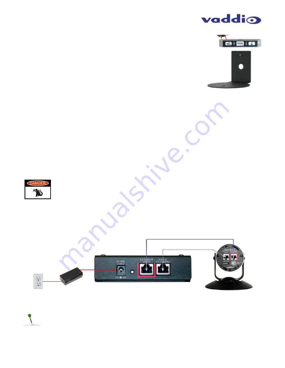
  Follow the sample wiring diagram for connecting the Cat-5 cables to the WideSHOT and USB Mini 

Interface (on the previous page, but read and understand the rest of these instructions especially the next note). 


NOTE:  

Check all Cat-5 cables for continuity in advance of the final connection.  Label the 

Cat-5 cables.  Plugging the EZ-POWER VIDEO cable into the wrong RJ-45 may cause 
damage to the camera system and void the warranty.  For premise cabling, please use real 
RJ-45 connectors and crimpers.  Please don’t use the pull through or EZ type of RJ-45. 


STEP 3a:

  Connect a Cat-5 cable from the EZ-POWER VIDEO RJ-45 jack of the USB Mini to the EZ- 

POWER VIDEO jack of the Vaddio camera. 


STEP 3b:

  Connect a Cat-5 cable from the RS-232 TO CAMERA RJ-45 jack on the USB Mini to the RS-232 

serial control port of the Vaddio camera.  


Diagrams:  Connecting the USB Mini 


STEP 4:  

Place the camera onto the camera mount and use the provided ¼”-20 screws to secure the camera to 

the mount.  To dress the cabling, push the extra cable back into the wall opening.   
 

HINT

:  A small piece of black fabric or felt attached to the back of the mount (wall-side) with a small slit to 

allow cables through may help the overall dressing of the mount and cables.


STEP 5:  

Connect the supplied 24 VDC, 2.08 Amp switching power supply to the USB Mini. Plug in the AC power 

cord to the power supply and connect it to a local power outlet.  Verify the blue LED power light on the USB Mini 
and the blue LED on the Vaddio camera are illuminated. 

STEP 3a 

STEP 3b 

STEP 5 

Cat-5 

Cat-5 

Содержание WIDESHOT WALLVIEW MINI 999-6911-100

Страница 1: ...f 32 VADDIO WIDESHOT WALLVIEW MINI Wide Angle HD Point of View Camera System with a 82 2 Horizontal Field of View and the Quick Connect USB Mini Interface Model Number 999 6911 100 North America Model...

Страница 2: ...WideSHOT WallVIEW Mini WideSHOT WallVIEW Mini Document Number 342 0710 Rev A Page 2 of 32 Inside Front Cover Blank...

Страница 3: ...ails 13 Framing the WideSHOT s Video Shot 14 Drawing A Small 10 wide x 12 long Conference Room with a WideSHOT HD 14 Drawing A Bigger Small Room 12 wide x 16 long Conference Room with WideSHOT HD 14 C...

Страница 4: ...egotiate The USB Mini also offers easy mounting either on wall or under table with an integrated mounting tab similar to the style used on Vaddio EZCamera Interface Module or EZIM This provides the en...

Страница 5: ...l pack out One 1 Quick Connect USB Mini Interface 998 1105 039 One 1 6 1 83m USB 2 0 Type A Male to Type B Male Cable Black One 1 24 VDC 2 0 Amp Power Supply One 1 Euro Power Cable One 1 UK Power Cabl...

Страница 6: ...urled screw 2 The Manual Iris Control After setting the zoom range and focusing on the subject s at the distance that the camera will be used the iris can be adjusted to limit the amount of light that...

Страница 7: ...as follows Table WideSHOT Dip Switch Settings 4 HD Video Select A rotary switch allows the user to choose the HD output video resolution and format After setting or changing the resolution reboot the...

Страница 8: ...3 115mm x 1 57 40mm x 1 1 28mm LED Indicator Red LED illuminates when transmitting IR brightness indicates battery strength Compatible Cameras Ships with ZoomSHOT and WideSHOT Compatible with all Vadd...

Страница 9: ...6 8 GREENGAIN 0 16 8 BLUEGAIN 0 16 8 REDGREEN 0 16 8 Combination Color Adjustment REDBLUE 0 16 8 Combination Color Adjustment BLUEGREEN 0 16 8 Combination Color Adjustment SATURATION 0 16 8 Chroma RET...

Страница 10: ...ion and operating note a The USB Mini interface will boot up in UVC streaming video mode A quick momentary touch will switch to web control mode and video will no longer pass This allows the administr...

Страница 11: ...escent lighting cells Cameras generally don t like to be swamped with fluorescent light and very few people sit on the ceiling anyway The Thin Profile Wall Mount for the WideSHOT can be mounted direct...

Страница 12: ...et the desired image orientation normal or flipped Set up the lens according to the directions on Page 6 Step 3 Follow the sample wiring diagram for connecting the Cat 5 cables to the WideSHOT and USB...

Страница 13: ...y to control the camera in real time The IR remote controller can control the camera s basic functions and enter the OSD on screen display for more advanced controls The IR remote is the best way to c...

Страница 14: ...work well in the room and excellent video is the result There are many room set up primers available on today s internet for reference Drawing A Small 10 wide x 12 long Conference Room with a WideSHOT...

Страница 15: ...PC media players Quick Time 10 2 VLC Media Player 2 0 4 Real Player 16 0 Compatibility Operating Systems Apple OS X 10 7 and above Windows XP w Service Pack 3 with known issues and errata Windows 7 L...

Страница 16: ...d by the administrator Assigning a user name can limit access to the admin menus by a general user By default the Username is blank and the password for the user account is password The administrator...

Страница 17: ...narios These lighting presets include Automatic Incandescent Hi Incandescent Lo Fluorescent Hi Fluorescent Lo and Outdoor character limitations are why the names are spelled so gnarly Set this control...

Страница 18: ...tion of one of the 6 factory scenes or any of the 3 user defined scenes 3 CCU Scenes Click on any of these 9 buttons to load one of the CCU scenes into the camera These scenes can be fine tuned if cha...

Страница 19: ...for the amount of Chroma Color Vibrancy desired A numeric value will be displayed in the box to the right of the slider Store CCU Scene button Once the desired scene adjustments have been made this bu...

Страница 20: ...per USB Mini basis The labels appear on every page at the top middle of the page Simply enter the room information and click Save Screen Shot Admin Menu Networking Under the Networking menu the Netwo...

Страница 21: ...ssword is also password The Network administrator can reassign the user name and password as well as the admin password There is only one user password and one admin password at any given time If chan...

Страница 22: ...nnect The file for the firmware update is chosen in this menu and the update is started here too Screen Shot Admin Menu Update Confirmation After clicking on Begin Firmware Update a confirmation pop u...

Страница 23: ...update load Again please don t interrupt the firmware load Screen Shot Admin Menu Help Service Help information can be found under the Help menu Support phone numbers and e mail manuals FAQ s and Syst...

Страница 24: ...the supplied Vaddio IR SHOT Commander or through IP over USB as described earlier through the USB Mini s web pages Make a test call to ensure the system is working properly VLC Media Player Example 1...

Страница 25: ...y Switch for Output Resolution Settings Thin Profile Wall Mount 535 2000 237 Provided with WideSHOT WallVIEW Systems Black powder coating Sized to fit on 1 gang wall box or with supplied drywall faste...

Страница 26: ...pliance This digital apparatus does not exceed the Class A limits for radio noise emissions from digital apparatus set out in the Radio Interference Regulations of the Canadian Department of Communica...

Страница 27: ...ressly approved by Vaddio can affect emission compliance and could void the user s authority to operate this equipment ICES 003 Compliance ICES 003 Issue 4 2004 This digital apparatus does not exceed...

Страница 28: ...Vaddio s technical support Provide the technician with a return phone number e mail address shipping address product serial numbers and original purchase order number Describe the reason for repairs...

Страница 29: ...ck Connect DVI HDMI SR Quick Connect USB and Quick Connect USB Mini Interfaces ONLY 568B Wiring Standard The video signals are differential HSDS and can only be processed by these interfaces Table Cam...

Страница 30: ...WideSHOT WallVIEW Mini WideSHOT WallVIEW Mini Document Number 342 0710 Rev A Page 30 of 32 SYSTEM NOTES...

Страница 31: ...WideSHOT WallVIEW Mini WideSHOT WallVIEW Mini Document Number 342 0710 Rev A Page 31 of 32 Inside Rear Cover Blank...

Страница 32: ...4 Vaddio All Rights Reserved Reproduction in whole or in part without written permission is prohibited Specifications and pricing are subject to change without notice or obligation Vaddio WideSHOT Zoo...

Отзывы: