


WallVIEW PRO 300
WallVIEW PRO 300 Installation and User Guide 341-668 Rev. B Page 6 of 10
Appendix 1: Cable Pin-outs for the WallVIEW PRO System
EZCamera Interface Module Pin-outs
Power Connector
Pin Signal
1 Power
+
2 Power
-
3 Power
+
4 Power
-
5 Power
+
6 Power
-
7 Power
+
8 Power
-
RS-232 IN Connector
Pin Signal
1)
DTR (Sony® Daisy chain to DSR)
2)
DSR (Sony Daisy chain from DTR)
3) Unused
4) Unused
5) Unused
6) Digital
GND
7)
RXD (from TXD of control source)
8)
TXD (to RXD of control source)
RS-232 OUT Connector
Pin Signal
1)
DSR (Sony Daisy chain from DTR)
2)
DTR (Sony Daisy chain to DSR)
3) Unused
4) Unused
5) Unused
6) Digital
GND
7)
TXD (to RXD of control source)
8)
RXD (from TXD of control source)
Video Connector
Pin Signal
SD
HD
1) IR+
IR+
2)
IR GND
IR GND
3) Y+ Y+
4) C+ PB+
5) C- PB-
6) Y- Y-
7)
Comp. Video +
PR+
8)
Comp. Video -
PR-
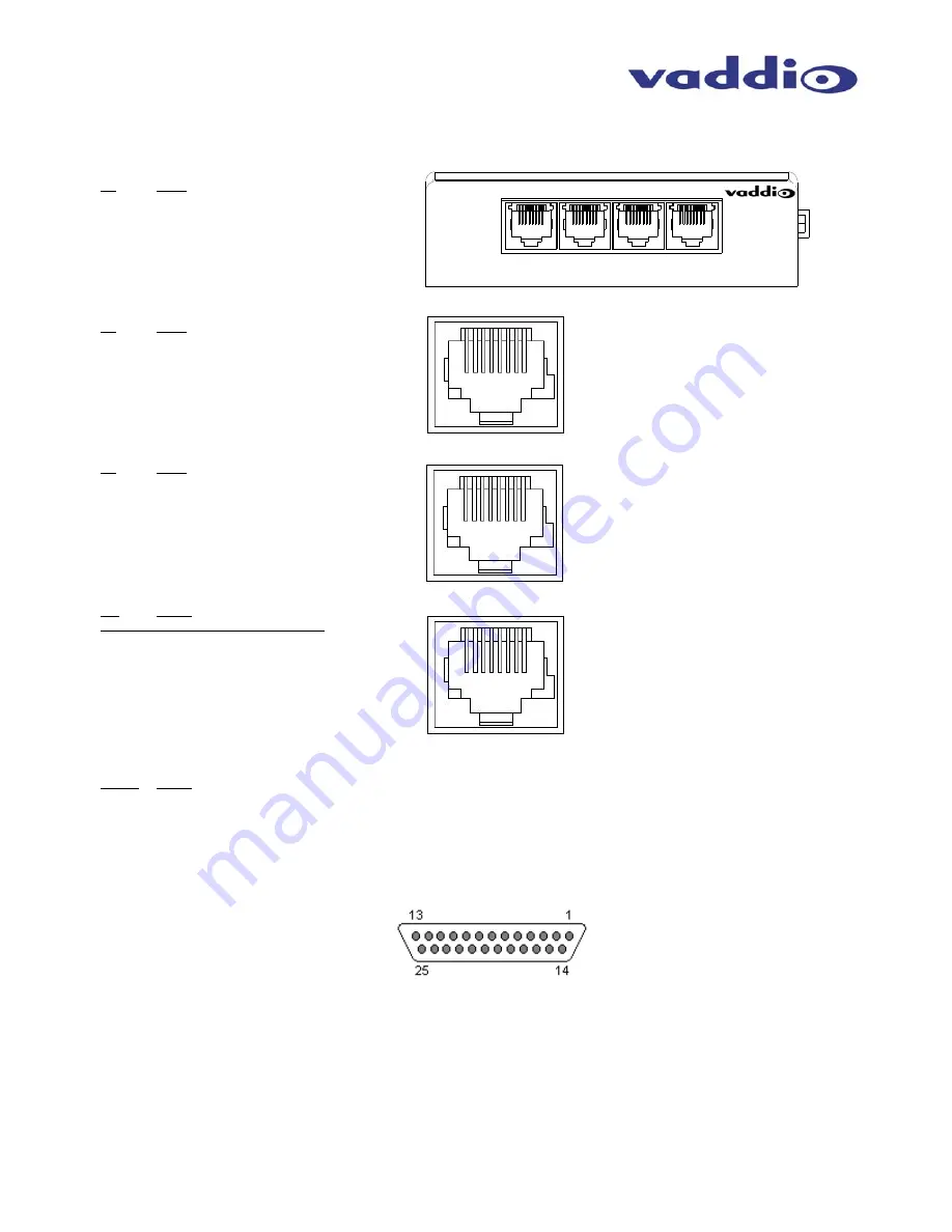
DB-25 Connector
Pins Signal
1 GND
Out
14
RXD Out
2 TXD
Out
15
DTR Out
3 DSR
Out
16
GND IN
4 TXD
IN
17
RXD IN
5 DTR
IN
18
DSR IN
6 IR
19
GND
7 GND
20
CVBS/PR
8 GND
21
C/PB
9 GND
22
Y/Y
10 GND
23
GND
11 GND
24
12V
12 12V
25
12V
13 12V
12345678
VIDEO
POWER
RS-232
OUT
RS-232
IN
EZIM
12345678
12345678


