Vaddio WallVIEW – Document Number – 010-2201-000 Rev. F
Page 3 of 8
INSTALLATION
The WallVIEW products are cameras specifically designed for installation on a
vertical wall surface with Cat. 5 cable connectivity for Power, Video and Control
signaling. Installation is simplified in that no custom 8-Pin mini-din cables or
expensive S-Video plenum cables are needed and no power outlets are required
near the camera bracket. All cabling is routed to the head-end using Cat. 5 cabling
with the EZCamera Cabling system.
Before
Installing
•
Locate the camera mounting location paying close attention to camera viewing
angles, lighting conditions, possible line of site obstructions, and checking for
in-wall obstructions where the camera is to be mounted. Pick a mounting
location to optimize the performance of the camera.
•
Pre-wire all cabling as required (see wiring diagram examples).
•
The WallVIEW 100, 70 and 50i can be mounted to standard 2-gang wall
boxes. All cameras are basically lightweight and the thin profile wall mount
bracket can be adequately secured to the wall with the four (4) provided
conical plastic wall anchors (or your choice of dry wall anchor).
Wiring
Diagram
Examples
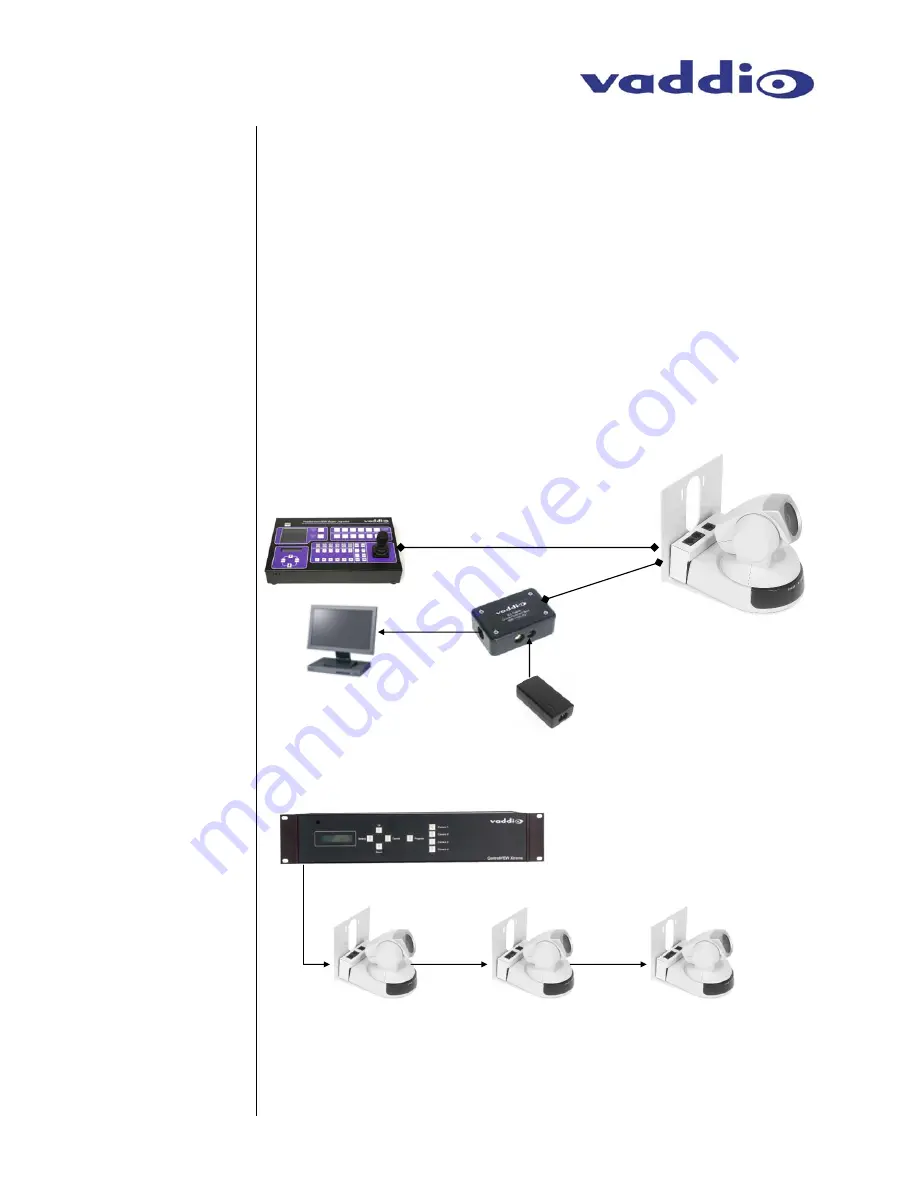
The Basic Idea
: WallVIEW 50i, 70 & 100 PTZ
Figure 2:
The WallVIEW 50i, 70 & 100 uses a single cat. 5 for Power and Video and a 2nd Cat. 5 for control.
Control is wired in a daisy chain configuration if a single control port is to be used.
Daisy Chain
Control
Configuration
Note:
TXD, RXD & GND are required for basic control. For Daisy Chaining, DSR and DTR are required for
Sony products (Pins 1 and 2 on the Cat. 5 cable) and CTS and RTS are Required for Canon products
(Pins 3 and 4 on the Cat. 5 cable).
ProductionVIEW
Super Joystick
RS-232
S-Video or
Composite
Video or Both
Cat. 5
Power to Camera
Video From Camera
WallVIEW 100 PTZ
with Camera, Shoe
and Mount
Cat. 5
Quick-Connect Box
Display, Projector
or Codec
Power Supply
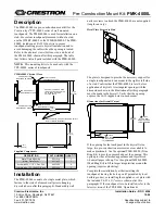
Figure 3:
Vaddio ControlVIEW™ Xtreme Camera
Controller with Single RS-232 Control Port
controlling 3 WallVIEW 100s in Daisy Chain
Configuration
RS-232
OUT
RS-232
IN
RS-232
OUT
RS-232
IN
RS-232
OUT
RS-232
IN


