VADDIO TrackVIEW Скачать руководство пользователя страница 5


TrackVIEW Install Guide 341-337 Rev. E 

Page 5 of 32 

TrackVIEW and Peripherals Install Guide 

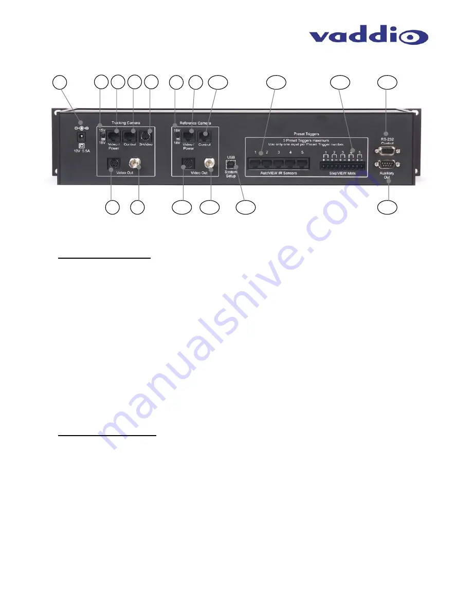
TrackVIEW Back Panel I/O and Controls 


1) Power 

Input 


a.  Note:  Use only the 18VDC Power Supply Provided with the TrackVIEW. 
 

Tracking Camera Section 
2)  15V/18V Power Switch 

a.  EZCamera Cat. 5 cabling runs for Video/Power have a 15V/18V power selection switch for Cat. 

5 power/video cables to match the cameras power requirements as the cable distance to the 
camera increases (15V for shorter Cat. 5 runs, 18V for longer runs - see Table 1, pg. 9). 

b.  For EZCamera Cat. 5 cabling runs for when using the EVI-HD1 as a tracking camera, an 

external power supply is used (cabling distances are up to 500 feet for video and power). 

3) Video/Power 

Jack 

a.  RJ-45 jack to carry power to the Tracking Camera and receive video from the camera over a 

Cat. 5 cable. 

4) Control 

Jack 

a.  RJ-45 jack to carry RS-232 to the Tracking Camera.   

5)  S-Video Input Jack  

a.  S-Video Input jack is for the S-Video output of the EVI-HD1 Quick-Connect PRO for the 

TrackVIEW HD1 System. 

6)  S-Video Output Jack 

a.  S-Video output to view system/monitor for Tracking Camera. 

7)  Composite Video Output (BNC)  

a.  Composite output to view system/monitor for Tracking Camera. 
 

Reference Camera Section 
8)  15V/18V Power Switch 

a.  15V/18V power selection switch for Cat. 5 power/video cables to match the reference cameras 

power requirements as the cable distance to the camera increases (see Table 1, pg. 9). 

b.  Wide Angle Lens is provided for the EVI-D70 Reference Camera (lens is included but may not 

be required depending on distance to, and width of, the presentation area).  

9) Video/Power 

Jack 

a.  RJ-45 jack to carry power to the Reference Camera and receive Video from the camera over 

Cat. 5 cable.  

10) Control Jack 

a.  RJ-45 jack to carry RS-232 to the Reference Camera.   

11) S-Video Output Jack 

a.  S-Video output to set-up monitor for Reference Camera. 

12) Composite Video Output (BNC)  

a.  Composite output to set-up monitor for Reference Camera. 

1

11

2

3

5

6

7

9

8

4

10

12

15

14

13

17

16

Figure 3: 

TrackVIEW Controller 
Rear Panel 

Содержание TrackVIEW

Страница 1: ...e triggered by mats or IR sensors Motion tracking can be disabled providing for only triggered preset tracking and preset tracking can be disabled allowing for only motion tracking First Step Last Ste...

Страница 2: ...op with a DB 9 RS 232 port The system software is intuitive and easy to use to maximize system performance and provide for quick set ups Note USB overrides serial port The serial port is disabled when...

Страница 3: ...W Kit with both Tracking and Reference Cameras two EVI D70s Part 999 7000 070 One 1 Vaddio TrackVIEW Controller IR Remote Power Supply Rack Ears and System Set up Software One 1 Sony EVI D70 PTZCam wi...

Страница 4: ...triggers are activated simultaneously 5 IR Window a IR window for use with Vaddio TrackVIEW IR Remote controller 6 Tracking Disable a Turns on off on off toggle camera tracking 7 Preset Disable a Turn...

Страница 5: ...Video Input jack is for the S Video output of the EVI HD1 Quick Connect PRO for the TrackVIEW HD1 System 6 S Video Output Jack a S Video output to view system monitor for Tracking Camera 7 Composite...

Страница 6: ...setting trigger presets see Figure 4 Program the remote by installing the batteries Press and Hold both the POWER and TRIGGER DISABLE 1 buttons for 5 seconds The unit is programmed 1 Power On Off Con...

Страница 7: ...VIEW 70 and TrackVIEW 100 dual camera kits see Figure 6 Both cameras use the EZCamera cabling shoe and are powered from the TrackVIEW controller Figure 5 EVI D70 Reference camera and Tracking Camera P...

Страница 8: ...mera for the Tracking Camera The EVI HD1 has a 12X optical zoom lens and will work well for any environment that demands the quality of a HD imaging device Both cameras use the EZCamera cabling shoe a...

Страница 9: ...both outputs are concurrently active Table 1 EZCamera Cabling Information Voltage settings and Maximum Cat 5 cable lengths for Video Power Vaddio Camera System Power Settings Cat 5 Cabling Distances E...

Страница 10: ...r from its own Quick Connect PRO EZIM and 36VDC power supply see Figure 10 The EVI HD1 uses Cat 5 cables for Video and Power 2 from the Quick Connect PRO and a 3rd Cat 5 for Control Connect the main v...

Страница 11: ...hed 75 cable Part 999 1511 000 Large 57 1 45m x 27 5 70cm with attached 75 cable Part 999 1512 000 Architectural Thin Presence Sensing Automatic Locator Mats two sizes for Concealed installations Smal...

Страница 12: ...ine another different preset than stored in the Presets 1 through 5 The multi step mode is commonly used with multiple presenters where two triggers can be programmed into a wide shot to pick up a lar...

Страница 13: ...etting 6 5 2m to 13 1 4m Adjust to height of ceiling height of IR Sensor installation Like any IR sensor the ceiling height will affect the overall IR zone size Table 4 below lists three common ceilin...

Страница 14: ...pport rails approx every 2 or 5 08cm line up with the holes in the sensor mounting flange Figure 18 With the provided sheet metal screws attach the tile support rails through the sensor mounting flang...

Страница 15: ...ment In this example when the presenter is not on a mat the Tracking camera will track them automatically as they walk between the mats or IR sensor Tracking is not recommended in a multi presenter en...

Страница 16: ...nector and restart the program Communication will be restored To Set up the Reference Camera Click on the Tracking tab and then on the Reference Camera The area will highlight in a gray color indicati...

Страница 17: ...the overall right edge of the reference camera s field of view then click Save Right Limit This sets the Tracking Camera s pan limits Click Save Tracking Preset and the Tracking camera is set Alternat...

Страница 18: ...etc of the Reference camera s field of view Editing the motion mask can mask these areas off Go to the Edit Motion Mask section The Clear Mask control removes whatever mask may be loaded The Set All...

Страница 19: ...y Set this parameter to best optimize the tracking speed and movement characteristics of the presenters and the camera used A camera that can pan faster should use lower values than cameras that move...

Страница 20: ...get Width defines the number of tracking blocks in width required to continue to be recognized as a target The minimum Active Target Width will be always equal to or larger that the Minimum Target Wid...

Страница 21: ...the button status in case the remote or front panel controls have been used to change the system configuration The Yellow Highlighted Parameters The yellow highlighted parameters on the Room Setup ta...

Страница 22: ...p or Last Step the set up is the same for both First or Last select which mode and disable the tracking by pushing the Tracking Disable button turn Tracking back on by pressing the button again after...

Страница 23: ...rs are triggered and activate a Multi Step preset When the camera presets are triggered the associated preset LEDs will blink then glow a solid blue when the camera PTZ setting is reached PUTTING IT A...

Страница 24: ...the stage area The gray area is the area that the presenter occupies Note the screen and whiteboard notches to eliminate any possibility of false movement information from screen movement reflections...

Страница 25: ...Mic Stand Mat 1 Mat 2 Mat 3 IR Sensor Ceiling Area Seating Area Screen Lectern Whiteboard Stage Background Mic Stand Mat 1 Mat 2 Mat 3 IR Sensor Figure 36 Preset 3 is the Screen position preset and i...

Страница 26: ...Set Tilt Speed 1 23 1 Slow 23 Fast ZoomSpeed x Set Zoom Speed 0 7 0 Slow 7 Fast Version Display Firmware Version ClrMem Clear EEPROM ClrPresets Clear All Presets Tracking RefCam x Set Reference Camer...

Страница 27: ...on RJ 45 EZCamera Cabling system with Video Power on single Cat 5 and S Video for use with EVI HD1 Quick Connect PRO Video Outputs Four 4 Total Reference Camera Two 2 Composite on BNC S Video on 4 pi...

Страница 28: ...ith a return phone number e mail address shipping address and product serial numbers Describe the reason for repairs or returns as well as the date of purchase Include your assigned RMA number in all...

Страница 29: ...y not cause interference and 2 This device must accept any interference including interference that may cause undesired operation of the device Changes or modifications not expressly approved by Vaddi...

Страница 30: ...tions on RJ 45s Pins 1 Unused 2 Unused 3 Unused 4 Unused 5 Unused 6 Digital GND 7 TXD 8 RXD AutoVIEW IR Sensors Power and Signaling Connections on RJ 45s Pins 1 18V 2 GND 3 Unused 4 Unused 5 Signal 6...

Страница 31: ...TrackVIEW Install Guide 341 337 Rev E Page 31 of 32 TrackVIEW and Peripherals Install Guide TrackVIEW NOTES...

Страница 32: ...ww vaddio com 2007 Vaddio All Rights Reserved Reproduction in whole or in part without written permission is prohibited Specifications and pricing subject to change TrackVIEW Quick Connect StepVIEW Au...

Отзывы: