VADDIO QUICK-CONNECT CCU Z700 Скачать руководство пользователя страница 3

Quick-Connect CCU Z700 

Quick-Connect CCU Z700 Installation and User Guide 341-718 Rev. B                                                                                  Page 3 of 12 

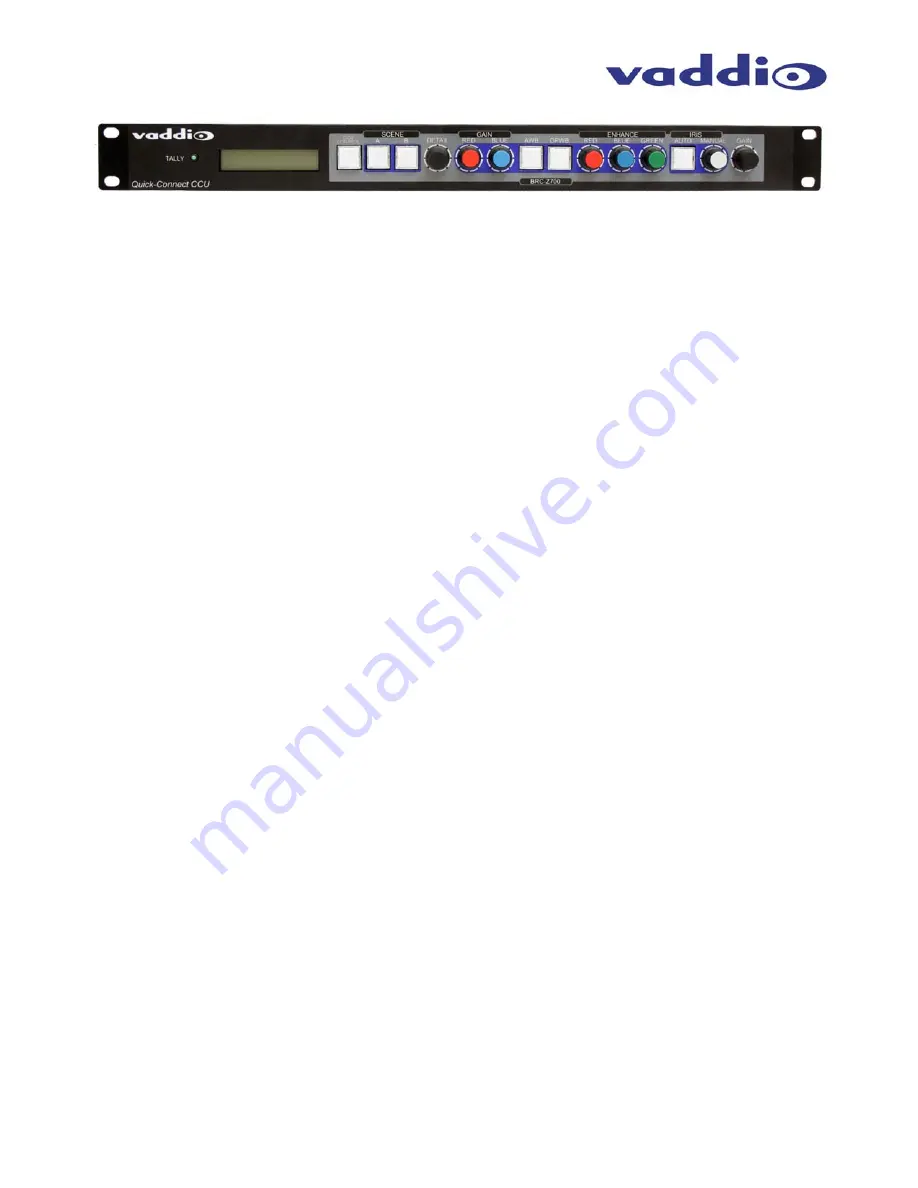
Quick-Connect CCU Front Panel Controls (left to right): 


Tally Light: 

The blue LED tally light on the front panel is tied to the tally contacts on the rear panel allowing the user to 
easily track which camera interface is being used in a multi-camera system by supplying a simple contact 
closure (i.e. from ProductionVIEW Super Joystick or ProductionVIEW HD). 
 

LCD Display: 

Backlit (blue) display indicates which mode is active (CCU CONTROL or PTZ CONTROL) and the value of 
the parameter being adjusted.  In CCU CONTROL mode, when a rotary encoder is touched, the name of the 
control being actuated and the value of that assigned parameter will be displayed.  
 

CCU Control Switch: 

Backlit (blue) SPDT switch, lit when activated, blocks the incoming PTZ controls on the RS-232 input and 
allows the end user to make adjustments to the camera image characteristics.  When off or deactivated, PTZ 
information is throughput to the camera and the front panel controls of the QCCU are deactivated to avoid a 
control issue or latency created by a master control string filtering program.  
 

Scene A and B: 

Two camera adjustment scenes (A & B) can be stored into microprocessor memory.  When lit (backlit blue 
SPDT switch), the scene is activated.  To store a scene, the user adjusts the camera to taste and touches 
and holds the scene button down until the button blinks. 
 

Detail:  

The Detail control sharpens or softens objects in the frame.  


Red Gain Control: 


The Red Gain encoder adjusts the red gain of the signal when AWB is disengaged. 

 
Blue Gain Control: 


The Blue Gain encoder adjusts the blue gain of the signal when AWB is disengaged. 

 
AWB:  


The Automatic White Balance controls/adjusts the color levels automatically when engaged.  Turn off AWB 
to manually adjust the Red and Blue levels, as well as Red, Green and Blue Enhance. 

 
OPWB:  


One-Push White Balance control allows the user to set the white balance with one push (the camera must 
see 60% of the image as white in order to operate).  OPWB overrides AWB and Red/Blue controls when 
activated. 
 

Enhance:    

The Red, Green and Blue Enhance controls can make fine adjustments to the color levels when AWB is 
disengaged. 
 

Auto Iris: 

The Auto Iris mode automatically adjusts the iris and gain of the camera.  To manually adjust the iris or gain, 
turn off this control. 
 

Manual Iris: 

The manual iris control allows the user to set the iris manual to one of the 18 settings available. 

 
Gain: 

The Gain control adjusts the overall gain of the camera.  To manually adjust the gain Auto Iris must be off.   

Содержание QUICK-CONNECT CCU Z700

Страница 1: ...store settings on two discrete Scene buttons and buttons for Auto White Balance One Push White Balance and Auto Iris Like all Vaddio Quick Connect systems the Thin Profile Wall Mount and mounting hard...

Страница 2: ...for power to ensure the motors receive the required current to operate properly The Video Cat 5 cable uses all four pairs for video The RS 232 Cat 5 provides communication to the camera for CCU and PT...

Страница 3: ...stment scenes A B can be stored into microprocessor memory When lit backlit blue SPDT switch the scene is activated To store a scene the user adjusts the camera to taste and touches and holds the scen...

Страница 4: ...transmitted through a differential amplifier to a receiver at the EZIM CCU The G L gain adjustment is on the EZIM CCU or the receive side of the signal Camera Feature Switches The QCCU interface has...

Страница 5: ...timize the performance of the camera Pre wire all cabling as required see wiring diagram examples The Thin Profile Wall Mount for the Quick Connect CCU Z700 can be mounted directly to a 3 gang wall bo...

Страница 6: ...dard connectors The basic system connectivity is illustrated in Figure 2 Note Plugging the POWER CAT 5 Cable into the wrong RJ 45 may cause damage to the camera system and void the warranty COMPLETING...

Страница 7: ...ideo feed to camera EZIM Tally 2 Pin Phoenix type spring cage connector Video Inputs BNC Connector for Sync Video Outputs BNC Connectors for HD Analog Component Y PB PR SD Composite Video RJ 45 Transp...

Страница 8: ...e user s authority to operate this equipment ICES 003 Compliance This digital apparatus does not exceed the Class A limits for radio noise emissions from digital apparatus set out in the Radio Interfe...

Страница 9: ...d 3 Not Used 4 Not Used 5 Not Used 6 GND 7 RXD from TXD 8 TXD to RXD RS 232 G L OUT Connector RJ 45 Pin Signal RS 232 1 Not Used 2 Not Used 3 Not Used 4 G L 5 G L GND 6 GND 7 TXD to RXD 8 RXD from TXD...

Страница 10: ...BS GND 3 Y Y 4 C PB 5 C GND PB GND 6 Y GND Y GND 7 Not Used PR 8 Not Used PR DB 25 Connector Pins Signal 1 CVBS GND 14 CVBS 2 G L GND 15 G L 3 NC 16 GND IN 4 TXD IN 17 RXD IN 5 NC 18 NC 6 NC 19 NC 7 G...

Страница 11: ...s and describe the reason for repairs or returns as well as the date of purchase and proof of purchase Include your assigned RMA number in all correspondence with Vaddio Write your assigned RMA number...

Страница 12: ...63 971 4464 www vaddio com 2008 Vaddio All Rights Reserved Reproduction in whole or in part without written permission is prohibited Specifications and pricing subject to change Vaddio Quick Connect H...

Отзывы: