background image

ELECTRICAL CONNECTION 

vacon • 21 

24-hour  support:  +358 (0)201 212 575 •  Email:  [email protected] 


Model 

Cross section 

NXV0010 

10mm

NXV0015 

10mm

NXV0020 

16mm

NXV0025 

16mm

NXV0030 

16mm

NXV0040 

25mm

NXV0050 

25mm

NXV0080 

35mm

NXV0100 

35mm

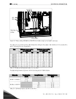
Table 5-5  Panel earthing cable dimensions 

The minimum cable cross section is calculated in compliance with loading capacity of cables. The 

recommended cross section is calculated in compliance with 1-% voltage drop for a cable 100 m in 

length. 


Содержание NXV0010

Страница 1: ...user s manual 3 phase photovoltaic inverters for connection to mains supply drives nxv0010 to nxv0100...

Страница 2: ...Y 7 3 1 Type designation code 7 3 2 Lifting the unit out of the transport packaging 7 3 3 Storage 8 3 4 Maintenance 9 3 5 Warranty 9 4 INSTALLATION 10 4 1 Free space around the cabinet 12 4 2 Fixing t...

Страница 3: ...WED TO CARRY OUT THE ELECTRICAL IN STALLATION RISK OF ELECTRIC SHOCK The solar inverter VACON 8000 SOLAR has been designed to be installed in enclosed places It shall be protected against harsh weathe...

Страница 4: ...e equipment PPEs must be used Helmet Safety goggles for electrical risk Safety footwear Electrically resistant gloves adequate for the voltage Protective gloves against mechanical risk Access to the p...

Страница 5: ...not form a part of the supply cable or cable enclosure shall in any case be not less than 2 5 mm2 if mechanical protection is provided or 4 mm2 if mechanical protection is not provided For cord connec...

Страница 6: ...Hz 0 5 Cos 0 99 for output 20 100 of Pn Harmonic distortion 2 5 for output 30 of power Consumption at night 5W NXV0010 NXV0030 30 W NXV0040 NXV0100 Maximum efficiency 94 96 Ambient temperature 10 40 C...

Страница 7: ...environment and rated voltage less than 1000V T fulfils standard EN61800 3 2004 when used in IT networks Option boards each slot is represented by two characters where A basic I O board B expander I...

Страница 8: ...o be kept in store before use make sure that the ambient conditions are acceptable Storing temperature 40 70 C Relative humidity 95 no condensation The environment should also be free from dust If the...

Страница 9: ...cor rosion on terminals busbars and other surfaces 5 7 years Change cooling fans main fan fan of the LCL filter 5 10 years Change DC bus capacitors if DC voltage ripple is high Table 3 1 Proactive ma...

Страница 10: ...on instructions included in this manual The IP21 protection of the VACON 8000 SOLAR inverter only allows for installation in enclosed places Note the locations of some essential components of the inve...

Страница 11: ...e The equipment has to be installed in a place where the room temperature is between 10 C and 40 C Lower temperatures prevent the equipment from starting up and higher temperatures limit the output po...

Страница 12: ...g air required is indicated in the table below Also make sure that the tempera ture of the cooling air does not exceed the maximum ambient temperature of the inverter 200 mm 800 mm 25 mm Figure 4 3 Sp...

Страница 13: ...net can be fixed to the floor alone or to the floor and the back wall 4 2 1 Fixing the unit to floor alone For the floor only mounting the fixing points in all four bottom corners of the cabinet shown...

Страница 14: ...p Flip it and refix the screws as shown in Figure 4 5 2 Then bolt the cabinet to the floor at the fixing points on the bottom front side see Figure 4 5 BOTTOM VIEW FRONT REAR Rear iron clamp Figure 4...

Страница 15: ...hich may cause death or serious injury 5 1 Electrical diagrams 5 1 1 NXV0010 to NXV0030 R BE1 RF5 340 800VDC 30A 3Ph 400V 50Hz 22A QA1 4 TB2 3 2 3 RA1 3 CA1 QA5 QA2 3 FC4 3 FA1 3 PE1 FCP 2 TA0 3 PE 3...

Страница 16: ...1 2121 Fax 358 201 212 205 5 1 3 NXV0080 to NXV0100 R BE1 RF5 340 800VDC 200A 3Ph 400V 50Hz 145A TB2 3 2 3 RA1 1 3 CA1 QA5 FC4 3 FA1 3 PE1 FCP 2 TA0 3 PE 3 PE1 01 QB1 FC3 2 RA1 2 3 QA2 3 I Figure 5 3...

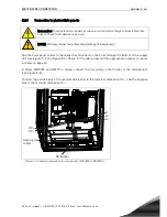
Страница 17: ...o which all the inverter s metallic parts are connected This connection terminal must be connected to earth Remember to earth the PE busbar See Table 5 1 on page 18 5 2 2 Connection to mains The termi...

Страница 18: ...mm2 AC DC PE AC DC PE NXV0010 1 5 6 10 50 95 240 NXV0015 1 5 6 10 50 95 240 NXV0020 1 5 6 10 50 95 240 NXV0025 1 5 6 10 50 95 240 NXV0030 1 5 6 10 50 95 240 NXV0040 10 10 10 240 240 240 NXV0050 10 10...

Страница 19: ...respective terminals on the drive through the bottom of the supply unit see Figure 5 5 and Figure 5 6 Check for the cable sizes and the appropriate number of cables in tables on page 20 In drives NXV...

Страница 20: ...2x95mm2 NXV0040 2x70mm2 2x 2x95mm2 4x 2x185mm2 NXV0050 2x95mm2 2x 2x95mm2 4x 2x185mm2 NXV0080 2x 2x70mm2 4x 2x95mm2 4x 2x185mm2 NXV0100 2x 2x95mm2 4x 2x95mm2 4x 2x185mm2 Table 5 3 Panel input cable di...

Страница 21: ...XV0020 16mm2 NXV0025 16mm2 NXV0030 16mm2 NXV0040 25mm2 NXV0050 25mm2 NXV0080 35mm2 NXV0100 35mm2 Table 5 5 Panel earthing cable dimensions The minimum cable cross section is calculated in compliance w...

Страница 22: ...de the control unit of the Vacon 8000 Solar inverter see Figure 5 8 Four different board types can be used with the inverter A1 A2 B5 C2 and D7 The control connections of these boards are described be...

Страница 23: ...T A1 option board Description Standard I O board with digital inputs outputs and analogue inputs outputs Allowed slots A Type ID 16689 Terminals Two terminal blocks coded mounting of blocks in wrong o...

Страница 24: ...nically connected to terminal 12 7 GND Ground for reference and controls Galvanically connected to terminals 13 19 8 DIN1 DigIN A 1 Digital input 1 Common CMA Ri min 5k 9 DIN2 DigIN A 2 Digital input...

Страница 25: ...de AI1 mode Voltage input 0 10V AI1 mode Voltage input 0 10V differential AI1 mode Voltage input 10 10V Jum per block X2 AI2 m ode AI2 mode 0 20mA Current input AI2 mode Voltage input 0 10V AI2 mode V...

Страница 26: ...OPTA1 parameters Number Parameter Min Max Default Note 1 AI1 mode 1 5 3 1 0 20mA 2 4 20mA 3 0 10V 4 2 10V 5 10 10V 2 AI2 mode 1 5 1 1 0 20mA 2 4 20mA 3 0 10V 4 2 10V 5 10 10V 3 AO1 mode 1 4 1 1 0 20m...

Страница 27: ...Jumpers None Board parameters None I O terminals on OPTA2 Terminal Parameter reference on keypad and NCDrive Technical information 21 22 23 RO1 normal closed RO1 common RO1 normal open DigOUT B 1 Rela...

Страница 28: ...igOUT X 1 Switching capacity 24VDC 8A 250VAC 8A 125VDC 0 4A Min switching load 5V 10mA 25 26 RO2 common RO2 normal open DigOUT X 2 Switching capacity 24VDC 8A 250VAC 8A 125VDC 0 4A Min switching load...

Страница 29: ...nector Description NC 1 No connection VP 2 Supply voltage plus 5V RxD TxD N 3 Receive Transmit data A RxD TxD P 4 Receive Transmit data B DGND 5 Data ground reference potential for VP You can use this...

Страница 30: ...mming tool The OPTD7 board is delivered with the transformer which is suitable for voltage range 380V 690V Please note that the transformer can not be used with the pulse width modulated PWM voltage i...

Страница 31: ...ransformer ratio Primary secondary 60 1 Transformer second ary output voltage range 14V rms Between the terminals L1 L2 L3 Input impedence L1 L2 50kOhm L1 L3 25kOhm L2 L3 25kOhm L3 is internal virtual...

Страница 32: ...rrent A Nominal voltage V Braking capacity kA Acting behaviour Fuse size Suitable fuse type Cat nr by Ferraz Shawmut NXV0010 No fuses needed NXV0015 NXV0020 NXV0025 NXV0030 NXV0040 160 1200 100 gPV 12...

Страница 33: ...y including the earth cable are correct ly connected Check that the main AC circuit breaker and possible auxiliary circuit breakers are connected and closed 3 Press the START button on the control pan...

Страница 34: ...fault RUN The inverter is running Indicates the order of phases in the mains STOP Indicates that the inverter is not running READY Illuminated when DC level is OK In case of a fault the symbol will no...

Страница 35: ...shows a description of the fault see chapter Active Faults 6 1 3 Text lines The three text lines provide the user with information about the current location within the menu structure of the panel sep...

Страница 36: ...top the inverter 6 1 5 Browsing the control panel Data on the control panel is arranged in menus and submenus Menus are used for example to dis play control signals and the measurements of reference v...

Страница 37: ...nal DC voltage V1 6 DC link voltage 0 1000 V 1839 Filtered DC link voltage in Volt V1 7 Unit temperature 50 200 C 1109 Temperature of the unit in Celsius V1 8 AC voltage 0 1000 V 1709 AC voltage measu...

Страница 38: ...here you were before the fault trip The fault is active until it is deleted with the Reset push button Normal state no faults 6 1 5 3 Fault history menu M5 The Fault history menu can be accessed from...

Страница 39: ...at least once a year Visually check the external condition of the inverter checking mainly the good condition of the door and its locking elements Visually check the internal condition of the inverter...

Страница 40: ...how to solve them THE SOLUTION FOR SOME OF THE PROBLEMS INDICATED HERE IMPLIES TO PER FORM CHECKING INSIDE THE INVERTER THE WIRES OF AC MAINS OR THE DC WIRES IN THE SOLAR PANELS THESE CHECKS HAVE TO B...

Страница 41: ...11 Input phase supervision Input line phase is missing Check supply voltage fuses and cable 13 Frequency con verter under temperature Heatsink temperature is under 10 C 14 Frequency con verter over t...

Страница 42: ...or near to you Please visit http www vacon com wwcontacts html 41 IGBT tempera ture IGBT Inverter Bridge overtemperature protection has detected too high a short term overload current Check loading 44...

Страница 43: ...limit Check AC Voltage 74 FreqOverLimit AC frequency on line side is above the max limit Check AC Frequency 75 FreqUnderLimit AC frequency on line side is below the min limit Check AC Frequency 76 DC...

Страница 44: ...Vacon distributor...

Отзывы: