


2 EASY
DMR21 DOOR STATION
1. Basic function:
2. DIP switch setting:
3. Modules:
Press buttons to call monitor, and press talk button on monitor to con-
versation, press unlock button to unlock.
Router Mode:
The
Router Mode
is used for the big capacity system which has plen
-
ty of apartments for blocks with BDU unit. The namelist can be updat-
ed by SD Card or DT-Config (More details refer to
Update Namelist
Section
).
Work Mode Set to
2
, and ID code set to
0~3
.
Gateway Mode:
The
Gateway Mode
is used for the community network system, the
common door station is connected in the system which can call all the
monitors. Besides, if the door station is connected in each block,it can
call the monitors in the block.
Work Mode set to
3
, and ID code set to
0~3
.
* Cancel
# Save
(0~3)
[ 2 ]
5. Work Mode [0]
* Cancel
# Save
(0~3)
[ 0 ]
1. ID Code [0]
Input Mode
: In standby mode. Input #8001+ Code ( 66666666 by
default), then select “ 5 ” item to set the
Doorplate Mode
, for exam-
ple input 13-02 to call the monitor. As the following picture shows: 13
means the 13th floor, and 02 means the second room numbe.
* Cancel
# Save
[ * * * 1 1 - 1 1 ]
5. Doorplate Mode [11]
0: *
1: 123
2: ABC
3: -
* Cancel
# Save
(0~3)
[ 3 ]
5. Work Mode [0]
* Cancel
# Save
(0~3)
[ 0 ]
1. ID Code [0]
Input Mode
: In standby mode. Input #8001+ Code ( 66666666 by
default), then select “ 5 ” item to set the
Doorplate Mode
, for example
input 3-06 to call the monitor. As the following picture shows: 3 means
the third BDU, and 06 means the ID code of monitor is 06.
* Cancel
# Save
[ * * * * 1 - 1 1 ]
5. Doorplate Mode [11]
0: *
1: 123
2: ABC
3: -
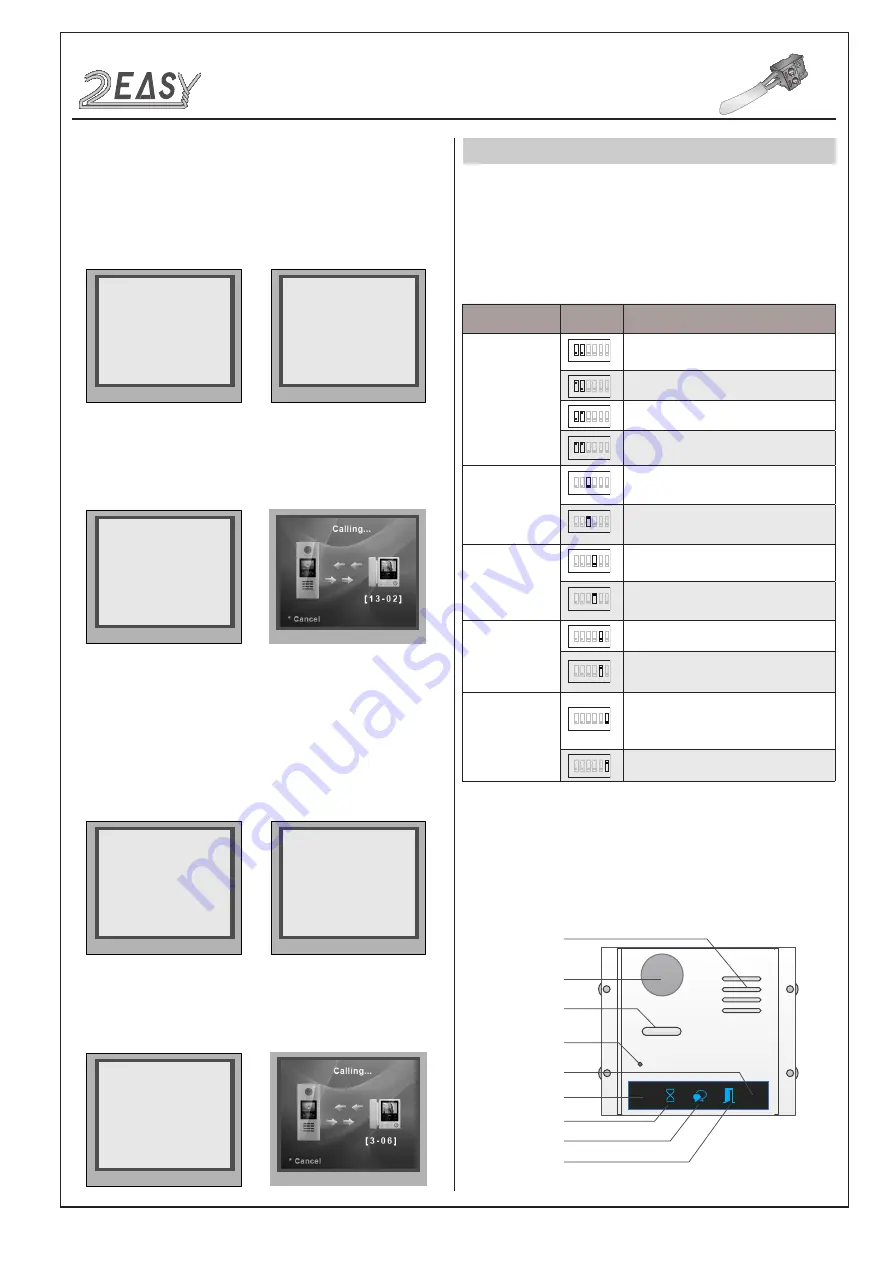
Bit definition
Bit state
Function Descriptions
Bit-1 and Bit-2
(door station ID
setting)
1 2
3 4 5 6
ON
Default setting, ID = 0, setting for the first door
station
1 2
3 4 5 6
ON
ID = 1, setting for the second door station
1 2
3 4 5 6
ON
ID = 2, setting for the third door station
1 2
3 4 5 6
ON
ID = 3, setting for the fourth door station
Bit-3
(single or double row
button setting)
1 2
3
4 5 6
ON
Default setting ,set "OFF " when using a
double row button door station
1 2
3
4 5 6
ON
Set "ON" when using a single row button door
station
Bit-4
(button code select)
1 2 3
4
5 6
ON
Default setting, set "OFF " when using the
default codes of the button
1 2 3
4
5 6
ON
Set " ON " when using the programmed codes
of the button.
Bit-5
(unlock time quick
setting)
1 2 3 4
5
6
ON
Default setting, unlocking time = 1 second.
1 2 3 4
5
6
ON
Unlocking time = 5 seconds.(can be changed
by software)
Bit-6
(cryptic key setting)
1 2 3 4 5
6
ON
Default setting, normally key A and key B is
not useful(about the position of key A and key
B,please refer to part 2)
1 2 3 4 5
6
ON
Activating the key A and key B is allowed.
Speaker
Camera lens
Night view LED
MIC
Invisible key A
Status indicator
Talk indicator
Unlock indicator
Invisible key B
1) Camera Module:
Parts and functions
DT System Test Manual
-3-


