28
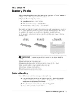
Figure 24. Self-locking connector button
Procedure
1
Connect the power cable between the high-voltage box and the battery module.
The self-locking connector's color should correspond to the battery module terminal's color: orange
corresponds to the positive pole, and black corresponds to the negative pole.
The internal wiring of the battery cabinet is the same. This chapter takes a battery cabinet as an example to
introduce.
Please take care of the removed battery module protective cover in case of backup.
2
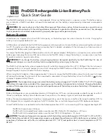
Connect the power cable between the RESS battery modules.
The wiring diagram of the battery inside of the battery cabinet is as follows:
Figure 25. The wiring diagram of the inside of the battery cabinet