Copyright © 2022 Dun Cat B.V. & THLAB, All rights reserved.
UUGear is a trade name of Dun Cat B.V.
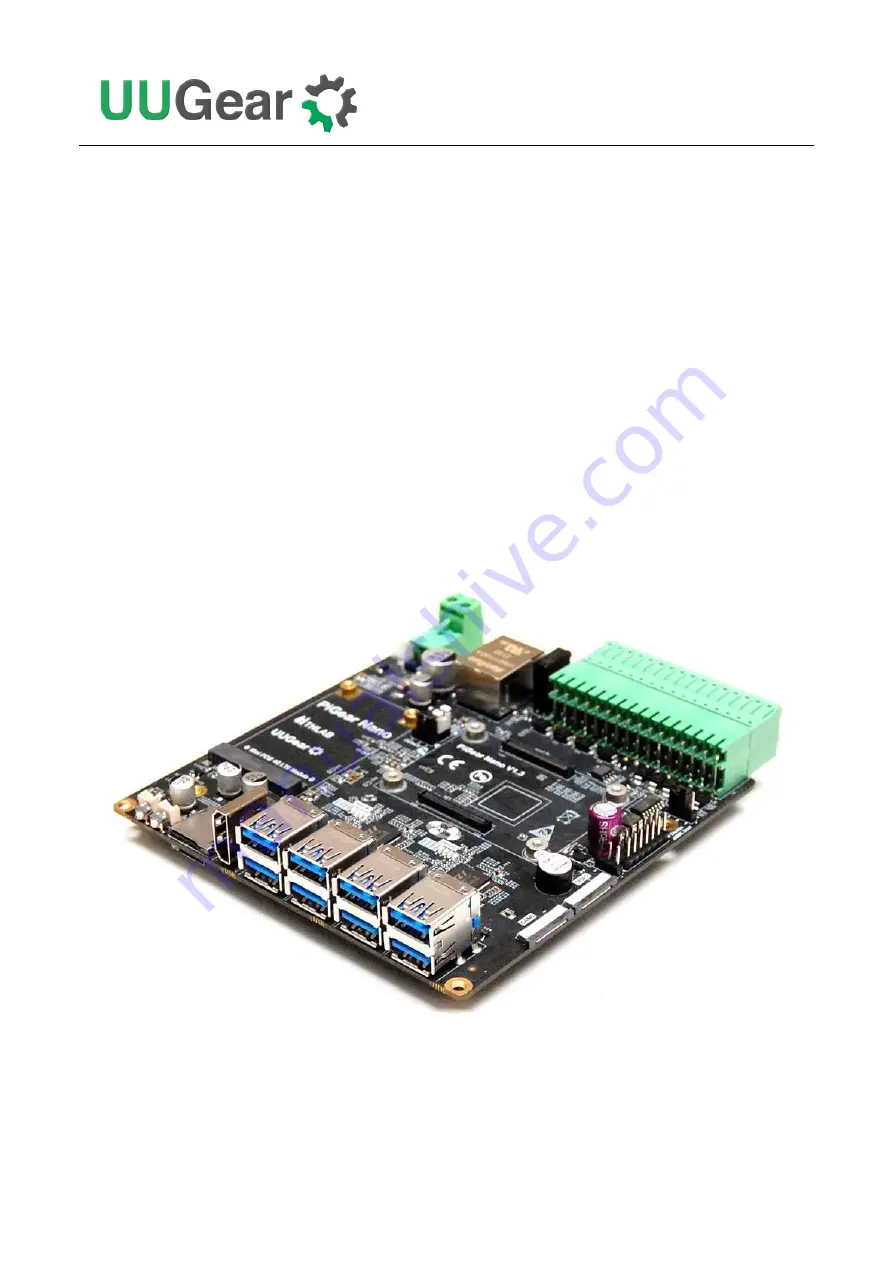
PiGear Nano:
Nano-ITX Raspberry Pi Compute Module 4 Carrier Board
User Manual
(revision 1.04)
Страница 1: ...Copyright 2022 Dun Cat B V THLAB All rights reserved UUGear is a trade name of Dun Cat B V PiGear Nano Nano ITX Raspberry Pi Compute Module 4 Carrier Board User Manual revision 1 04...
Страница 2: ...or Raspberry Pi CM4 Lite without eMMC 8 6 Powering PiGear Nano 9 7 Software Installation Update 9 8 Jumper Settings 11 9 Software Usage 14 9 1 Realtime Clock 15 9 2 Analog Inputs ADC 16 9 3 Digital In...
Страница 3: ...7 Configurable Digital Inputs Outputs 32 11 PCIE 35 11 1 NVME SSD 36 11 2 4G LTE Module 36 11 3 USB3 0 38 12 Realtime Clock RTC 39 13 DSI and CSI 40 14 SD Card Slot 41 15 LED Indicators 41 16 Buzzer...
Страница 4: ...cations but you can also use it as office computer family media center gaming console etc PiGear Nano offers a wide range of resources and interfaces Please see below the diagram for details There are...
Страница 5: ...2...
Страница 6: ...2 x 2 RS485 x 2 CAN x 1 Wire interface x 1 Storage NVME SSD M 2 interface x 1 Micro SD card slot x 1 for Compute Module 4 Lite only Display HDMI Type A connector x 1 MIPI DSI interface x 1 Camera MIPI...
Страница 7: ...30 C 80 C 22 F 176 F Humidity 0 80 RH no condensing No corrosive gas 3 Package Content Each package of PiGear Nano contains PiGear Nano board x 1 6x6x5 heat sink x 1 for VL805 chip on the back of the...
Страница 8: ...nd four metal standoffs and four screws in the package Just place the standoff under the mounting hole and use a screw to secure it Connect Raspberry Pi Compute Module 4 to the board by simply alignin...
Страница 9: ...screws not included in the package It is also recommended to put the small heatsink included in the package on the VL805 chip on the back of the board Because this chip could get rather hot if the bo...
Страница 10: ...the e latch power switch so your PiGear Nano board will be powered even without the operating system The bypass switch jumper is on the left of Raspberry Pi CM4 above the Default On jumper as shown in...
Страница 11: ...r example you can use Win32DiskImager under Windows or use dd command under Mac OS X or Linux You can also use Raspberry Pi Imager for any operating system After flashing the OS disk image into the bo...
Страница 12: ...u will still need to set the jumper correctly to make it work Note when e latch power switch is in used after the power is fully cut please wait a few seconds before trying to boot your PiGear Nano ag...
Страница 13: ...ll need to modify the UWI configuration file uwi conf in uwi directory You will see host raspberrypi and you need to replace the raspberrypi with the actual IP address or accessible host name After re...
Страница 14: ...after installing the operating system into eMMC This jumper is part of the multifunctional 2x7 pin jumper which will be introduced later With the software installed the e latching power switch is supp...
Страница 15: ...N Boot up when powered Default OFF Tap the button to boot up There is a reset jumper near the green 2x16 quick cable connector and it is to define the behavior of the reset button If you short pin 1 2...
Страница 16: ...spberry Pi Compute Module 4 official I O board Please see below the descriptions 1 2 3 4 5 6 7 8 9 10 11 12 13 14 1 and 2 force USB booting if shorted 3 and 4 write protect the EEPROM if shorted 5 MXL...
Страница 17: ...cript You will see the software interface like this pi raspberrypi cd pgnano pi raspberrypi pgnano PiGearNano sh PiGear Nano Nano ITX Raspberry Pi Compute Module 4 Carrier Board Version 1 00 by Dun Ca...
Страница 18: ...e fully power off after shutdown this alarm can also be used to wake up your Raspberry Pi Alternatively you can also use this alarm as a watchdog using option 5 When watchdog is turned on the watchdog...
Страница 19: ...more information about the analog inputs here Analog Inputs ADC ADC 1 ADC 2 ADC 3 ADC 4 Scale 0 001000 0 001000 0 001000 0 001000 Code 1 1 1 1 Volt 0 005684 0 005684 0 005684 0 005684 1 Set data rate...
Страница 20: ...urrent values of digital inputs are listed here You can press ENTER to refresh the view You can find more information about the digital inputs here Digital Inputs DI 1 DI 2 DI 3 DI 4 0 0 0 0 1 Refresh...
Страница 21: ...nd more information about the digital output here Digital Outputs DO 1 DO 2 DO 3 DO 4 0 0 0 0 1 Set DO 1 output LOW 2 Set DO 1 output HIGH 3 Set DO 2 output LOW 4 Set DO 2 output HIGH 5 Set DO 3 outpu...
Страница 22: ...Test You can test the programmable LED here More specifically you can turn on the red LED by setting GPIO 26 BCM naming to HIGH the yellow LED will turn off when red LED is on This test will last for...
Страница 23: ...sed via http raspberrypi 8000 pgnano If you cannot access it most probably is because the host name raspberrypi is not resolved In such case please configure your UWI to use actual IP address or acces...
Страница 24: ...as the same layout as the soldering pads instead of the holes on the connector please pay attention to those numbers aside If you want to connect a wire cable to the connector you can just directly pl...
Страница 25: ...e 2x16 quick cable connector They occupy UART1 UART3 UART4 and UART5 and they aremapped to different devices in the system Name Mapped Device in System UART1 RS232 1 dev ttyAMA0 UART5 RS232 2 dev ttyA...
Страница 26: ...23 And here is the schematic for RS485 Both RS485 channels work in Half Duplex mode and they do not need additional I O pin to control the transmitting direction...
Страница 27: ...rk CAN Bus PiGear Nano has one CAN bus which can be access on pin 22 and 23 in the 2x16 quick cable connector PiGear Nano uses chip MCP2515 to provide CAN controller which talks to Raspberry Pi Comput...
Страница 28: ...master device which talks to Raspberry Pi Compute Module 4 via the I2C 1 interface Many 1 wire devices actually have 3 wires one for transmitting data which should be connected to pin 3 and the other...
Страница 29: ...ause MCP3424 uses 2 048V internal voltage reference each channel can directly measure up to 11 6V Remarks analog input can directly apply up to 11 6V and needs to have common ground with PiGear Nano M...
Страница 30: ...register in MCP3424 and you can make configurations by changing specific bits More details can be found in MCP3424 s datasheet Here is an example for measuring voltage up to 11 6V You can calculate th...
Страница 31: ...no higher than 11 6V In this case the formula is changed to 1 2 220 47 2 048 2 47 1 1 2 11 634 2 1 If you want to measure the current you will need to connect a sense resistor with the load in serial...
Страница 32: ...29 Usually is a rather small resistor If is 0 01 and the voltage drops on is 0 0125V the current can be calculated like this I 0 0125 0 01 1 25...
Страница 33: ...1 interface Each digital input can bear up to 12V Voltage below 0 5V is considered as LOW Note all four digital inputs are pulled down by default You can inquire the pin status via I2C 1 address 0x20...
Страница 34: ...rry Pi Compute Module 4 please see table below CM4 GPIO GPIO 11 GPIO 16 GPIO 17 GPIO 22 PiGear Nano DOUT DO 1 DO 2 DO 3 DO 4 Remarks every time you change the output value you need to give a rising ed...
Страница 35: ...3 DIO 4 Configuration 1 INPUT INPUT INPUT INPUT Configuration 2 INPUT INPUT OUTPUT OUTPUT Configuration 3 OUTPUT OUTPUT INPUT INPUT Configuration 4 OUTPUT OUTPUT OUTPUT OUTPUT When the pin is in OUTP...
Страница 36: ...le on inputs and you can monitor GPIO 23 and know when to query the new data 10 7 2 Configuration 2 DIO 1 and DIO 2 as inputs DIO 3 and DIO 4 as outputs In order to set DIO 1 and DIO 2 as inputs while...
Страница 37: ...d then 0xF6 This way you give bit 2 a raising edge to make the change take effect Bus Address Register Index Set to Value I2C 1 0x20 omitted 0xC0 B11000000 I2C 6 0x20 omitted 0xF4 B11110100 and then 0...
Страница 38: ...tted 0xFC B11111100 and then 0xFE B11111110 Then you set the output pin status via I2C 1 address 0x20 omitting register index More specifically set the value of bit 4 7 to change the output state on D...
Страница 39: ...VME SSD to it There is a green LED D12 on the top surface of PiGear Nano board and it will blink when SSD is transmitting data 11 2 4G LTE Module There is a Mini PCIE 4G LTE module connector on PiGear...
Страница 40: ...e you will need to set GPIO 6 to HIGH and GPIO 7 to LOW with these two commands Remarks you will then need to wait 5 10 seconds before running the lsusb command to see the 4G LTE module gets recongize...
Страница 41: ...have to work simultaneously Providing 8 USB 3 0 ports indeed unlock many possibilities and offers more flexibility Four stacked USB connectors are used and each of them has a dedicated 1A current lim...
Страница 42: ...ere is no need to use battery to keep the system time when the board is not powered PCF85063 has an alarm When this alarm is triggered it will pull down GLOBAL_EN on Raspberry Pi Compute Module 4 and...
Страница 43: ...1 instead of I2C 0 for DSI and CSI If you will use them please run these commands in home directory and then reboot You can run this command to test your camera connected to CAM0 pi raspberrypi sudo c...
Страница 44: ...3mm LEDs aside the Ethernet connector and they are in color red yellow and green The green LED serves as power indicator and will light up when PiGear Nano is turned on The red and yellow LEDs are bot...
Страница 45: ...Reset Button Connectors Aside the power button and reset button there are two small connectors Which allow you to connect external momentary push buttons and route them to different location 19 Case K...
Страница 46: ...out fan connector and power reset button connectors 1 02 2022 01 24 Add more details about enabling 4G LTE module Add more details about USB 3 0 1 03 2022 01 25 Add note about powering via USB type C...