The Utile Engineering Co. Ltd.
15/08/06
Irthlingborough, Northamptonshire. England
Tel: +44 (0) 1933 650216
Fax: +44 (0) 1933 652738
3 IC183
General
The normal routine of running the machine is very simple. If it is carried out strictly at all times, many years of
trouble free service can be expected.
We emphasise one point of paramount importance-
Filtration of incoming air of gas
If possible provide a logbook so that the operator can enter daily readings. After several months a record will show
whether the machine is performing as it did originally. If readings are to be taken the following are all that is
required. Inlet and outlet air temperatures, suction conditions and oil drip rate.
A typical layout for the logbook is shown in the table below.
Machine Log Book
Date
Inlet Air Temp.
Discharge Air Temp.
Suction Conditions
Operating Principle
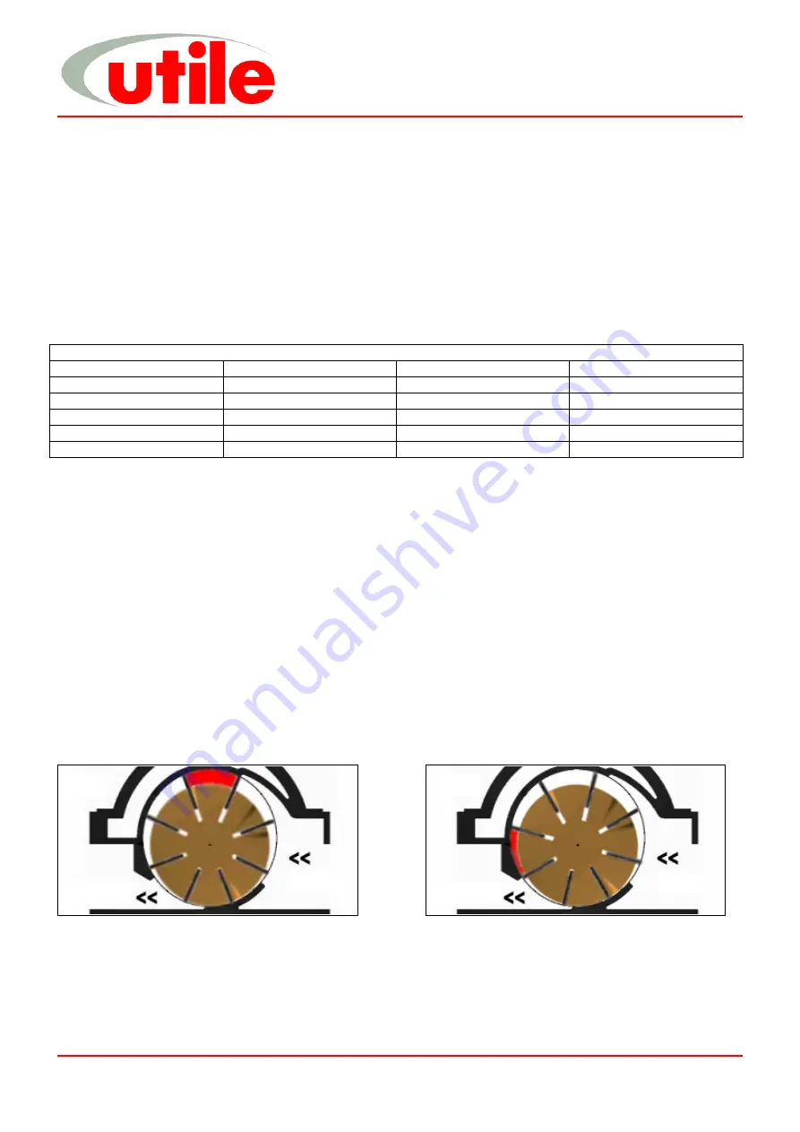
Rotary sliding vane compressors and vacuum pumps are multi-cell machines, which work on the displacement
principle. They provide a constant, low-pulsation supply of air or gas.
The machines have a cylindrical bored housing. The rotor, which is also cylindrical, is fitted eccentrically in the
cylinder so that a crescent-shaped working chamber is formed. Movable rotor vanes are fitted in the longitudinal
grooves in the rotor; centrifugal force and the force of the air or gas presses the blades against the cylinder-housing
wall when the rotor turns.
The vanes divide the crescent-shaped working chamber into cells of different sizes. As the rotor turns, the cell
volume on the intake side increases, and the cell draws air in at low pressure, at which point is open to the intake
delivery line. As the rotor continues to turn, the cell is closed (see fig 1) and the volume of the cell decreases. This
causes the enclosed air or gas to be compressed (see fig 2) and forced out through discharge delivery line under
atmospheric pressure.
The machine can only be run in one direction, which is indicated by an arrow on the cylinder. The direction of
rotation must not be reversed.
Fig. 1
Discharge
Intake
Fig. 2
Discharge
Intake
General
Operating Principle


