6
June 2011
06-237172-001 Rev AA
TROUBLESHOOTING
Before troubleshooting the system, check the following items:
•
Verify all mechanical and electrical connections are secure
and tight.
•
Verify all system wiring is correct.
•
Verify there is a proper system ground. The igniter, flame
sensor, and ignition module must share a common ground
with the burner.
Nuisance shutdowns are often caused by a
poor or erratic ground.
•
Perform the instructions in “Checkout” on page 4, as the
first step in any troubleshooting.
•
Verify that the system is powered and that the thermostat is
calling for heat.
•
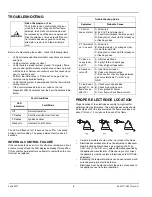
If the control proceeds to an error code on the red
diagnostic LED, troubleshoot per the Fault Conditions table
below:
The LED will flash on for 1/4 second, then off for 1/4 second
during a fault condition. The pause between fault codes is 3
seconds.
INTERNAL CONTROL FAILURE
If the control detects an error in its software or hardware, all out-
puts are turned off and the LED displays a steady ON condition.
If this condition persists after an attempt to restart then the con-
trol must be replaced.
PROPER ELECTRODE LOCATION
Proper location of the electrode assembly is important for
optimal system performance. The electrode assembly should
be located so that the tips are inside the flame envelope and
about 1/2 inch (1.2 cm) above the base of the flame.
•
Ceramic insulators should not be in or close to the flame.
•
Electrode assemblies should not be adjusted or disassem-
bled. Electrodes should have a gap spacing of 0.125±
0.031 inch (3.12± 0.81 mm), unless otherwise specified by
the appliance manufacturer. If this spacing is not correct,
the assembly must be replaced. Electrodes are NOT field-
adjustable.
•
Exceeding the temperature limits can cause nuisance lock-
outs and premature electrode failure.
•
Electrodes must be placed where they are not exposed to
the appliance user in normal operation.
WARNING
Risk of Explosion or Fire
The 35-63J ignition control cannot be ser-
viced by the user. If any control faults are
detected, the 35-63J control module must
be replaced by qualified service personnel.
Risk of explosion or fire can result if the con-
trol module has been opened or with any
attempts to repair it, and the warranty is
void.
Fault Conditions
LED
Indication
Fault Mode
Off
Normal Operation
2 Flashes
Pilot flame without call for heat
3 Flashes
Ignition Lockout
Steady On
Internal Control Failure
Troubleshooting Guide
Symptom
Probable Cause
1. Control
does not start
A. Mis-wired
B. 24 VAC Transformer bad
C. Fuse/Circuit breaker bad (no power)
D. Bad control, check LED for steady on
or flashing codes.
2. Thermostat
on - no spark
A. Mis-wired
B. Bad thermostat, no voltage at ther-
mostat terminal THS
C. Bad control, check LED for steady on
or flashing codes.
3. Valve on -
no spark dur-
ing TFI
A. Shorted electrode
B. Verify 1/8th inch spark gap.
C. Check high voltage cable.
4. Spark on -
valve off
A. Gas Valve coil open
B. Valve wire disconnected
C. Bad control, check voltage between
gas valve terminals PV or MV and
GND.
5. Flame okay
during TFI - no
flame sense
after TFI
A. Check electrode position
B. Check high voltage wire
C. Poor ground at burner
D. Poor flame, check flame current


