4
June 2011
06-237172-001 Rev AA
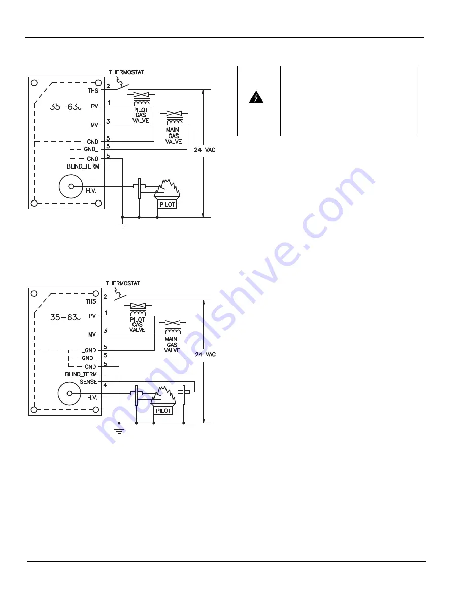
WIRING DIAGRAMS
Figure 3. Local Sense Wiring
Figure 4. Remote Sense Wiring
CHECKOUT
Test the gas control system after any service or component
changes to the appliance using the following method:
1.
Perform a visual check of all piping, burners, and venting.
Check all wiring for integrity and proper electrical and
ground connections. Verify the pilot burner is properly
grounded.
2.
With the gas supply and thermostat off, turn on power to
the appliance.
3.
Turn the thermostat to a setting high enough to initiate a
call for heat. Verify the ignition control proceeds through
the operating sequence to a safety shutoff (lockout) condi-
tion. (The burner will not light because the gas is shut off)
4.
Turn off the thermostat.
5.
Turn on the gas supply, and purge the gas lines of air.
Check for gas leaks on all joints upstream of the gas valve
with a soap solution.
6.
Turn the thermostat to a setting high enough to initiate a
call for heat. Verify the ignition control proceeds through
the operating sequence to a normal run (burner lit) condi-
tion. Confirm there are no gas leaks downstream of the
gas valve using a soap solution.
7.
Turn the thermostat setting down below the room temper-
ature. Verify the main and pilot burner flames go out.
WARNING
Risk of Explosion or Fire
Verify there are no gas leaks by using a rich
soap and water solution on all joints and
pipe connections. Never use a match or
lighter to test for the presence of gas. Fail-
ure to test properly before operation can
lead to explosion or fire and may result in
severe injury or death.

