37
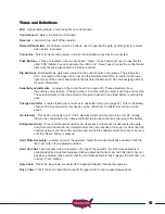
Installing Photo Eye For Vehicular Protection Only
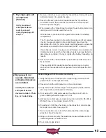
The photo eye must be wired as shown and the correct dipswitches must be turned on for the PEPM
software to work correctly. Detailed instructions are below with illustration.
NOTE:
Monitored UL325 photo eye installation instructions refer to page 18 step 11a.
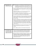
1. Connect photo eye power wire +12 vdc to J2 pin 12.
2. Connect photo eye power ground to J2 pin 2 or pin 7.
3. Wire the RX relay N/O contact from the photo eye to J2 pin 11.
4. Wire the RX relay common from the photo eye to J2 pin 2 or 7.
5. Turn OFF DS1 switch 3 and 4 (temporarily to provide power for installation)
6. Turn on dipswitch DS1 switch 10 photo eye power enable.
7. Install Photo eye and adjust beam – verify proper operation.
8. Once installed turn ON DS1 appropriate dipswitches for gate 1 or gate 2 or both for dual gates.
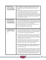
Test photo eye for proper operation, when gate is closing and beam is broken gate should stop and
reverse to full open. If gate is open and beam is broken gate will not close.
NOTE: Power is applied to photo eye just before gate operation begins and turns off when
gate stops.
DS1 dip switch 10 -
Photo Eye Power
Management Enable
Содержание PATRIOT RSL
Страница 60: ... 800 878 7829 USAutomaticGateOpeners com ...


