


18
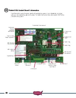
Installing Monitored Entrapment Protection Devices
Effective January 12, 2016 A vehicular gate operator or vehicular barrier (arm) operator shall have
provisions for, or be supplied with, at least two independent entrapment protection means as specified
in current UL325 standard Table 31.1. At installation, both entrapment protection devices must be
installed and operational before gate operation is allowed.
USAutomatic control boards utilize Type A (Inherent entrapment protection system) as the first
entrapment protection means identified. This is designed into the control boards for all USAutomatic
operators. The second entrapment identified must be a monitored Type B1 or Type B2 device that is
UL325 2016 listed.
SYSTEM MANUFACTURED AFTER JAN. 12, 2016 WILL NOT OPERATE WITHOUT 1 OF THE 2
FOLLOWING TYPES OF MONITORED ENTRAPMENT PROTECTION DEVICES CONNECTED
AND OPERATIONAL.
When the installation requires more than 1 monitored contact edge or 1 monitored photo eye, the
Monitored Entrapment Device Expansion Module must be installed. (USAutomatic Part# 500015)
Monitored Photo Eye (Type B1) Installation
for Entrapment Protection ONLY.
Connect wires per the table below: All wiring should be done with power disconnected from control board.
Photo Eye wiring for Entrapment Device Protection
Photo Eye Connections
Patriot Control Board Connections
Power +12 vdc
J2 pin 12
Power ground / O
J2 pin 2 or pin 7
Common
J2 pin 2 or pin 7
N/C contact
J2 pin 8
The energy saving design of the control board will only apply 12 vdc to the photo eye when the gate
is in operation. During instal12 vdc power is required to align the photo eye beam.
Set control board DS1 dipswitches as follows for the installation:
Control Board Dipswitch Settings for Installation
DS 1 switch 3
OFF – press down on the left hand side
DS 1 switch 4
OFF – press down on the left hand side
DS 1 switch 10
ON – press down on the right hand side
11
11a
Содержание PATRIOT RSL
Страница 60: ... 800 878 7829 USAutomaticGateOpeners com ...