15
REVISION 1.0, 1-19-15
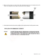
1. Remove membrane element from the right (feed water) side of the membrane housing. Long nose pliers
may be necessary to pull the old membrane element out of the membrane element housing.
2. Lubricate the membrane brine seal and cap o-rings with a non-petroleum based lubricant.
3. Install membrane through the right side (feed water) of the membrane housing with brine seal located on
the feed water side.
4. Push the membrane in the housing from right to left (brine seal on the right). Once the membrane is in
place make sure it is fully seated in the housing.
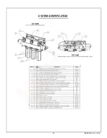
5. Lubricate the O-rings on the cap and re-install the cap (6, Figure 1.A) on the right side by gently twisting
it, while pushing it onto the housing. Ensure that you do not pinch or fatigue any O-rings while re- in-
stalling the end plug. Push the end plug on until the outer diameter of the plug is flush with the outer di-
ameter of the pressure vessel. Lubricating the inner and outer O-rings will make the cap installation easi-
er.
6. Insert the two half-moon retaining disks until they are fully seated. Subsequently fasten
using a #5 Allen wrench.
7. Reconnect any fittings that may have been disconnected when the membrane pressure vessels were dis-
assembled.
8. To Start-Up the system, please refer to the Initial Start-Up section of this manual.
CAUTION: WET MEMBRANES ARE SHIPPED IN A PRESERVATIVE SOLUTION. THE
MEMBRANES MUST BE FLUSHED FOR AT LEAST 30 MINUTES TO RE-
MOVE THE PRESERVATIVE FROM THE MEMBRANE. DISCARD ALL OF THE
PERMEATE, WHICH IS PRODUCED DURING THE FLUSH PERIOD.
Содержание L1-200
Страница 1: ...1 REVISION 1 0 1 19 15 US Water Systems 300 GPD Premium Wall Mount Light Commercial RO System...
Страница 9: ...9 REVISION 1 0 1 19 15...
Страница 10: ...10 REVISION 1 0 1 19 15...
Страница 11: ...11 REVISION 1 0 1 19 15...
Страница 12: ...12 REVISION 1 0 1 19 15 SYSTEM IDENTIFICATION...
Страница 17: ...17 REVISION 1 0 1 19 15 SPECIFICATIONS...
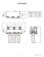
Страница 24: ...24 REVISION 1 0 1 19 15 SYSTEM DRAWING...
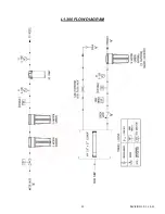
Страница 25: ...25 REVISION 1 0 1 19 15 L1 300 FLOW DIAGRAM...
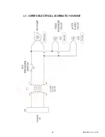
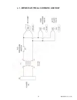
Страница 26: ...26 REVISION 1 0 1 19 15 L1 SERIES ELECTRICAL SCHEMATIC 110V 60HZ...
Страница 27: ...27 REVISION 1 0 1 19 15 L1 SERIES ELECTRICAL SCHEMATIC 220V 50HZ...


