E N G L I S H
44
reading.
When measuring below-ambient
temperatures, adjust the connection
between the thermocouple and the surface
until you get the lowest temperature
reading.
When measuring near - ambient
temperatures, take the reading when the
display is most stable.
Follow these steps to measure temperature:
1. Set the rotary switch to the “TEMP”
position.
2. Plug the thermocouple adapter into the
COM input terminal and the TEMP input
terminal observing the proper polarity.
3. Plug a K-type thermocouple probe
connector into the thermocouple adapter
observing the proper polarity.
4. Read the temperature on the LCD.
5. RS-232C INTERFACE
5.1 Introduction
RS-232C is an EIA-defined standard for a
serial communications interface commonly
used between computers, terminals, and
modems.
This Meter is capable of RS-232C interface
with a WINDOWS computer by using its bi-
directional RS-232C serial interface cable
and its WINDOWS software supplied as
optional accessories along with this Meter.
5.2 Interfacing the meter with a
Personal Computer
Follow these steps to interface the Meter
with a WINDOWS computer:
1.
Connect the RS-232C cable to the
computer’s 25-pin serial port. Plug the D9
male connector into the RS-232C terminal
on the back of the Meter.
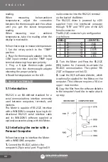
The RS-232C driver is powered by ±12V
supplied from the interfaced computer
through “DTR” and “RTS” pins of the D25
female connector.
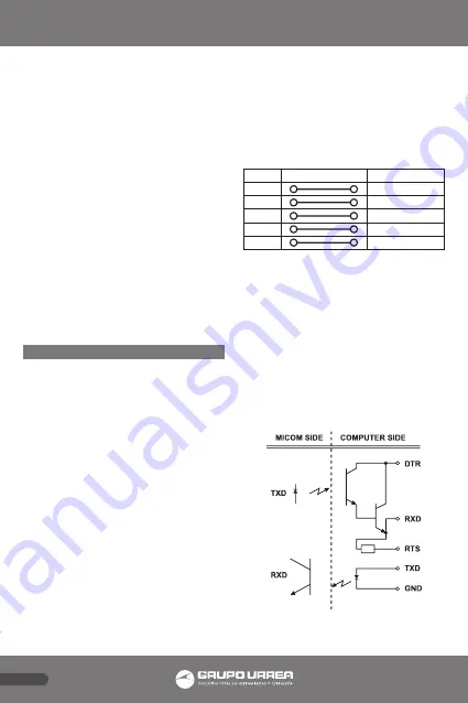
The RS-232C connector’s pin configuration
is as follows:
<DMM>
<COMPUTER>
2
3 RXD
3
2 TXD
4
20 DTR
5
7 GND
7
4 RTS
2.
Turn the Meter and Press the RS-232C
(REL) button for 2 seconds to activate the
RS-232C communication. The symbol ‘RS-
232C’ will appear on the LCD.
3.
Load the DOS software diskette, which
is optionally supplied for the Meter, on the
computer. This software requires a VGA or
upper - class monitor.
4.
Copy the files from the software diskette
to the computer’s hard disc to make a back-
up copy.


