background image

Installation & Operation Manua

l

REV 14-10-24


Page 12 of 19

PV-Shelter RMSxxF Series 


Battery wiring – batteries are wired in PARALLEL.  Use the 2 black jumper cables to connect all of the black 

4. 

terminals together, and use the 2 red jumper cables to connect all the red terminals together. 


Attach the black main negative battery power cable coming from the ECM to one of the negative battery 

5. 

terminals.


Remove the inline fuse and attach the red fused main positive battery power cable coming from the ECM 

6. 

to one of the positive battery terminals.


Use wire ties to tidy up wiring and tuck neatly out of the way.

7. 

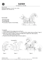
Installed solar panel on shelter roof.

figure 12. Installed solar panel on shelter roof

Determine solar panel positioning then mark and drill holes for mounting to the shelter roof ribs. 

8. 


Drill a hole through the roof for routing the solar panel wiring into the power module.  The hole should 

9. 

line up with one of the larger wire feed through holes in the power module base.


Route the solar panel wires through to the power module then secure panels to the roof using security 

10. 

screws provided. 

Caution – do not short the solar panel positive leads to the negative leads or to any part of the metal work on 

the chassis or shelter.  Use electrical tape to insulate leads when routing solar panel wiring. 


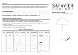
For the RMSxxF when there are two or more solar panels, the panels are wired in parallel.  Connect both 

11. 

positive solar leads to the positive (red) lead from the ECM as shown. Connect both negative solar leads to 

the negative (black) lead from the ECM.  Use marrettes (wire nuts) to make connections. 


Hold the power module lid up and make the connection for the luminaire to the control module as shown. 

12. 


Coil up any excess wiring and use wire wraps or zip ties to neaten up and tuck away all wiring.

13. 


Содержание RMS-F Series

Страница 1: ...REV 14 10 24 PV Shelter RMSxxF Installation Operation Manual Transit Solar powered LED Lighting System...

Страница 2: ...tion Page 4 How it Works Page 5 Data Logging Retrieval Assembly Page 9 Installation and Assembly Page 15 Troubleshooting Page 16 Maintenance Product Care Batteries Contact and Re order Information Pag...

Страница 3: ...t models are identical except for solar array size The size required depends on the local solar conditions required lighting levels and duration as well as shelter construction Safety Information NOTI...

Страница 4: ...e Energy Control Module is the central control of the lighting system It controls battery charging and regulates the power to the LED luminaires The ECM also monitors the system performance to ensure...

Страница 5: ...PROPRIETARY BC Canada V8X 4K1 Victoria DOCUMENT MAY BE REPRODUCED STORED IN A RETRIEVAL SYSTEM OR TRANSMITTED IN ANY TOLERANCES APPLY AS SHOWN BELOW FORM WITHOUT THE WRITTEN PERMISSION OF INTERPRET D...

Страница 6: ...Installation Operation Manual REV 14 10 24 Page 6 of 19 PV Shelter RMSxxF Series figure 2 Power module figure 3 Power Module with LID removed shown with ECM and batteries...

Страница 7: ...oria BC Canada ALL RIGHTS RESERVED NO PART OF THIS DOCUMENT MAY BE REPRODUCED STORED IN A RETRIEVAL SYSTEM OR TRANSMITTED IN ANY FORM WITHOUT THE WRITTEN PAGE DRAWN BY D HANKE DATE 07 07 2012 REVISION...

Страница 8: ...Installation Operation Manual REV 14 10 24 Page 8 of 19 PV Shelter RMSxxF Series figure 6 ECM with Solar LED and battery connections figure 7 Battery jumper harnesses...

Страница 9: ...aled against water There shall be no exposed wiring on the roof or interior of the shelter and the contractor must use appropriate conduit and electrical connectors in order to provide a professional...

Страница 10: ...ps 4 7 can be performed before the module is mounted to the shelter ceiling as it may be easier to do in the shop it is at the discretion of the installation crew It will make mounting to power module...

Страница 11: ...ng hazardous short circuit currents Remove all jewelry bracelets metal strap watches rings before attempting to handle or disassemble the battery pack Contact Urban Solar if further instruction is req...

Страница 12: ...a hole through the roof for routing the solar panel wiring into the power module The hole should 9 line up with one of the larger wire feed through holes in the power module base Route the solar pane...

Страница 13: ...ctivation the LEDs will flash 3 times quickly pause and then flash slowly giving one to four flashes depending on the state of charge of the batteries If the lights do not flash the system requires tr...

Страница 14: ...void for systems that are not installed within 6 months of delivery by Urban Solar Corp Replace the power module lid and secure with Torx Security fasteners provided 15 The RMSxxF installation process...

Страница 15: ...ge falls to less than 11 9V the ECM protects the battery from over discharge by disconnecting power to the luminaires Once the system has had sufficient time and sunlight to recharge and the battery v...

Страница 16: ...is required IMPORTANT MAINTENANCE NOTE Over time dirt and debris may collect on the solar module panel Excess dirt or grime will reduce battery charging and thus can lead to premature battery failure...

Страница 17: ...SHEET CAD REFERENCE 10430 COPYRIGHT 2008 BY Urban Solar Corp Victoria BC Canada ALL RIGHTS RESERVED NO PART OF THIS X XX DECIMALS 18 02 2009 DRAWN BY David Hanke DATE 07 04 2009 REVISION D HANKE Urba...

Страница 18: ...rban Solar Corp Victoria BC Canada ALL RIGHTS RESERVED NO PART OF THIS DOCUMENT MAY BE REPRODUCED STORED IN A RETRIEVAL SYSTEM OR TRANSMITTED IN ANY FORM WITHOUT THE WRITTEN PAGE DRAWN BY D HANKE DATE...

Страница 19: ...hereunder other than they shall meet the manufacturer s current sales specifications Any recommendations made by manufacturer concerning the use design or application of said goods are believed relia...

Отзывы: