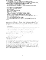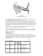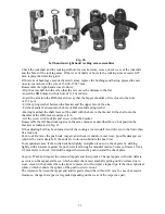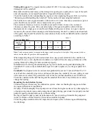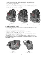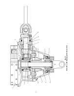
Fig. 61.
Mounting the driven gear of the
speedometer drive
Fig.57
Fig.58
Fig.59
Fig.60
345-943
- Set and tighten up seven bolts fastening the gear case cover, the tightening torque being
6.4
-
7.8 Nm
- Having turned the shaft for about 120 degrees anticlockwise by a wrench and sunk it in axial
direction to 8 mm minimum cock spring of the kick-starter and free the shaft. The shaft should
get out of the cover and lock (Fig.57).
- Set the gearshift sleeves in the neutral position by turning the reverse gear shift lever
backwards and check the shafts for ease of rotation;
- Fails the clutch shaft rotate easily, jump it into the hole for the slider, same with the main shaft
on the flexible coupling plate using mandrels (Fig.58 and 59).
- Check operation of starter mechanism and its spring.
The tolerable axial movement of the starter shaft is 1.0 mm.
- Press the plate onto the splines using device 345-943, fasten and splint (Fig. 60).
- Set the kick-starter lever, put distance washer onto the starter shaft, insert fastening wedge
knocking it with a aluminum hammer and tighten. The torque is 15.7
-
19.6 Nm.
For reassembly of the speedometer drive and clutch release mechanism refer to relevant sections
of this manual.
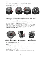
Fig. 62.
Setting the thrust bushing.
62
Содержание 750cc Series
Страница 1: ...Repair Manual 750cc All Models www imz ural com ...
Страница 2: ......
Страница 50: ...Fig 40 Removing the valve springs Fig 41 Measuring the side play between the valve and bush guide 50 ...
Страница 71: ...1 2 3 4 5 6 7 8 Fig 66 Final drive 71 ...
Страница 75: ...1 2 3 4 5 6 7 8 9 10 11 12 13 14 15 16 17 18 Fig 67 Final drive with disengageable sidecar drive 75 ...
Страница 98: ...Fig 11 iring Diagram 9 W 98 ...


