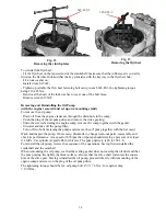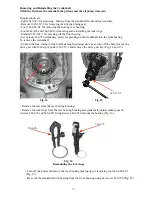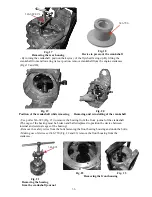
When the motorcycle has the disc brake insert a plate about 4 mm thick to prevent the brake pads
from getting out of the caliper. To reinstall the front wheel on the motorcycle, perform the above
operations in reverse order. When reassembling the axle in place, lubricate it with motor oil.
To remove the rear wheel proceed as follows:
- Remove the cotter pin of the axle slotted nut, unscrew the nut, loosen the swinging fork left-
hand arm clamp bolt nut and remove the axle together with the protective cap;
- When the motorcycle features the sidecar drive, disconnect the sidecar drive from the final
drive.
- Undo the butterfly nut of adjustment rod of rear brake
- Shift the wheel o
f
f the brake shoes to the left and remove the wheel from the frame
To reinstall the rear wheel on the motorcycle, perform the above operations in reverse order.
When reassembling the axle in place, lubricate it with motor oil. In fitting the wheel on the brake
shoes, the coupling splines sometimes may not coincide; therefore turn the wheel until the
coincidence of the splines is ensured. Adjust the rear wheel brake.
To remove the sidecar wheel:
- Take out the cotter pin, undo the nut and remove the protective cap;
- Insert a stand under the sidecar frame, lift the sidecar wheel and remove it.
To reinstall the sidecar wheel, reverse the sequence of the operations. Prior to mounting,
lubricate the axle with motor oil. The tightening torque of wheel axles should be 54
-
77 Nm.
7. REMOVING AND REINSTALLING THE FINAL DRIVE
To remove the final drive together with the propeller shaft, proceed as follows:
- Set the motorcycle on the stand and remove the rear wheel (see subsection 6);
-
Remove
the wing nut of the rear brake tie-rod, the nuts of studs fastening the final drive to
the swinging fork arm;
- Detach the final drive from the swinging fork arm and remove it from the rear. Take the
flexible joint flange off the propeller shaft to facilitate its passing through the hole in the swing-
ing fork girder. To reinstall the final drive, reverse the sequence of operations.
The tightening torque of the final drive to the swinging fork should be 30
-
34 Nm.
8. REMOVING AND REINSTALLING THE HANDLEBAR WITH CONTROL CABLES
AND SWITCHES
To remove the handlebar with all the control cables and switches:
- Remove the gasoline tank (see subsection 5);
- Disconnect the throttle cables from the carburetors (see subsection 5), the clutch
cable (see subsection 1), the front brake cable from the brake drum cover; for this
purpose, turn in the adjusting screw and set it so that its slot coincides with the bracket slot.
Engage the brake lever on the cover and remove the cable sheath tip from the seat in the
adjusting screw, then take the cable tip out of the lever;
- Undo the master cylinder hose (for motorcycle with disc brake).
- Disconnect the switch conductors from the motorcycle wiring plug connectors;
- Undo the nuts fastening the handlebar brackets to the fork cross-piece and remove the
handlebar.
If it is necessary to remove the switches, slacken clamping screws, while in the right switch undo
the screw fastening the body (with spherical head).
Reverse the sequence of the operations when reinstalling the handlebar. The tightening torque of
the bracket nuts should be 39
-
49 N m.
24
Содержание 750cc Series
Страница 1: ...Repair Manual 750cc All Models www imz ural com ...
Страница 2: ......
Страница 50: ...Fig 40 Removing the valve springs Fig 41 Measuring the side play between the valve and bush guide 50 ...
Страница 71: ...1 2 3 4 5 6 7 8 Fig 66 Final drive 71 ...
Страница 75: ...1 2 3 4 5 6 7 8 9 10 11 12 13 14 15 16 17 18 Fig 67 Final drive with disengageable sidecar drive 75 ...
Страница 98: ...Fig 11 iring Diagram 9 W 98 ...

