Page 3-7
Maintenance
3.5 - Switch Adjustments
TL38 Service & Parts
B
OOM
R
EST
L
IMIT
S
WITCH
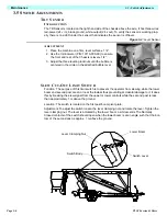
Function: This limit switch is activated when the booms are fully stowed and the lower boom is
sitting in the boom rest. The outriggers can only be operated when this switch is activated. The
limit switch lever is actuated by the lower boom when is sits into the boom rest. When the boom
leaves the boom rest the Normally Open contacts of the limit switch open and power is cut to the
outrigger function switches.
Location: The switch is located on the chassis assembly.
Adjustment: The switch should be activated when the boom sits in the boom rest. The lever is
non-adjustable,but should be checked for freedom of movement and kept clean from dirt and
other contaminants that might affect its free movement.
O
UTRIGGER
L
IMIT
S
WITCHES
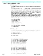
Function: These four limit switches are wired in series.
When the four outriggers are deployed these switches are activated and allow the booms func-
tions to be operated.
Location: Between the outrigger pivot plates.
Adjustment: The lever is non-adjustable and should be depressed by the outrigger cylinder head
when the outriggers are deployed. It should be checked for freedom of movement and kept clean
from dirt or other contaminants.
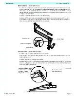
Function: This limit switch is activated when the booms are fully stowed and the lower boom is sitting in the boom rest. The outriggers can only be operated when this switch is activated. The limit switch lever (or ball :- pre-serial number 1008) is actuated by the lower boom when is sits into the boom rest. When the boom leaves the boom rest the Normally Open contacts of the limit switch open and power is cut to the outrigger function switches.
Location: The switch is located on the chassis assembly.
Adjustment:
The switch should be activated when the boom sits in the boom rest. The lever is non-adjustable,but should be checked for freedom of movement and kept clean from dirt and other contaminants that might affect its free movement.
Boom Rest
Switch Lever
Switch Body
Lever Clamping Nut
Ensure lever is free
to rotate as shown
Outrigger cylinder moves
in this direction when the
outrigger touches
the ground
Содержание TL38
Страница 1: ...ERVICE PARTS MANUAL POWERED ACCESS WORK PLATFORM TL38 ...
Страница 2: ......
Страница 4: ......
Страница 51: ...Page 3 28 Maintenance 3 17 Torque Specifications TL38 Service Parts NOTES ...
Страница 59: ...Page 5 2 Schematics 5 1 Introduction TL38 Service Parts ...
Страница 60: ...Page 5 3 Schematics 5 1 Introduction TL38 Service Parts ...
Страница 61: ...Page 5 4 Schematics 5 1 Introduction TL38 Service Parts ...
Страница 62: ...Page 5 5 Schematics 5 1 Introduction TL38 Service Parts ...
Страница 63: ...Page 5 6 Schematics 5 1 Introduction TL38 Service Parts Notes ...
Страница 66: ...Page 6 3 Illustrated Parts Breakdown General Assembly TL38 Service Parts ...
Страница 70: ...Page 6 7 Illustrated Parts Breakdown Booms Posts Assembly TL38 Service Parts ...
Страница 72: ...Page 6 9 Illustrated Parts Breakdown Platform Assembly TL38 Service Parts ...
Страница 84: ...Page 6 21 Illustrated Parts Breakdown Outrigger Cylinder Assembly TL38 Service Parts NOTES ...
Страница 86: ...Page 6 23 Illustrated Parts Breakdown Electrical Assembly TL38 Service Parts ...
Страница 92: ...Page 6 29 Illustrated Parts Breakdown Decal Assembly TL38 Service Parts ...
Страница 94: ...Page 6 31 Illustrated Parts Breakdown Decal Assembly TL38 Service Parts ...
Страница 95: ...Page 6 32 Illustrated Parts Breakdown Decal Assembly TL38 Service Parts NOTES ...

