Page 3-24
Maintenance
3.17 - Disassembly, Cleaning, Inspection and Assembly of cylinders
TL50 Service & Parts
I
NSTALLATION
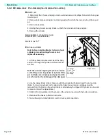
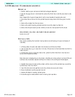
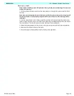
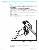
Note: before installing outrigger Cylinder check cylinder pins and bearings for wear and
replace if necessary.
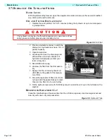
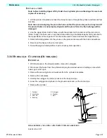
1. Installation is the reverse of removal (above)
Note: take care in aligning the pin in the holes so that the pin can be pushed in by hand. If
the pin and holes are not properly aligned and the pin is forced in, the bushings will be
damaged.
2. Test with weight at rated platform load to check system operation
3.17 D
ISASSEMBLY
, C
LEANING
, I
NSPECTION
AND
A
SSEMBLY
OF
CYLINDERS
Note: The disassembly, cleaning and inspection and assembly for all the cylinders is basically
the same.
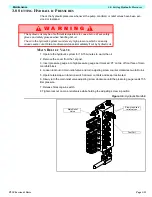
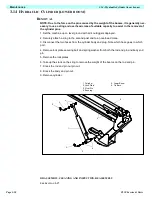
DISSASSEMBLY OF HYDRAULIC CYLINDERS
Note: Prepare a clean work area on which to service the internal parts.
1. Remove fittings, Pilot operated check valve cartridges and overcentre valve cartridges from
the cylinder blocks.
2. Bend up tab on tab washer (if applicable).
3. Unscrew end cap and remove from cylinder body with rod and piston.
4. Unscrew the piston locknut from the rod and remove the piston head and the end cap.
Note: Some piston locknuts are fitted with a roll pin and grub screw which must be removed
before unscrewing the locknut.
5. Remove all seals from the end cap (i.e. wiper, shaft seal, O-ring, rod seal, end cap gland and
PTFE seal) and disregard.
6. Remove all seals from piston head (i.e. piston O-ring and piston seal) and disregard.
CLEANING AND INSPECTION
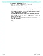
1. Clean all metal parts in solvent and blow dry with filtered compressed air.
2. Check all threaded parts for stripped or damaged threads.
3. Check the bearing surfaces inside of the end cap, outer edge surface of the piston, inside the
cylinder body and the rod for signs of scoring or excessive wear.
4. Replace any parts found unserviceable.
5. Discard all seals.
6. Examine all cartridge valves for wear on threads and damage to O-rings.
Содержание 503502-000
Страница 1: ...ERVICE PARTS MANUAL POWERED ACCESS WORK PLATFORM TL50...
Страница 21: ...Page 16 TL50 Service Parts Specifications Notes...
Страница 51: ...Page 3 30 Maintenance 3 19 Torque Specifications TL50 Service Parts NOTES...
Страница 59: ...Page 5 2 Schematics 5 1 Introduction TL50 Service Parts...
Страница 60: ...Page 5 3 Schematics 5 1 Introduction TL50 Service Parts...
Страница 61: ...Page 5 4 Schematics 5 1 Introduction TL50 Service Parts...
Страница 62: ...Page 5 5 Schematics 5 1 Introduction TL50 Service Parts...
Страница 63: ...Page 5 6 Schematics 5 1 Introduction TL50 Service Parts Notes...
Страница 66: ...Page 6 3 Illustrated Parts Breakdown General Assembly TL50 Service Parts 1 1 2 3 4 5 6 7...
Страница 68: ...Page 6 5 Illustrated Parts Breakdown Chassis Assembly TL50 Service Parts Chassis Assembly 503001 000...
Страница 70: ...Page 6 7 Illustrated Parts Breakdown Booms Posts Assembly TL50 Service Parts 44 45...
Страница 72: ...Page 6 9 Illustrated Parts Breakdown Platform Assembly Standard TL50 Service Parts...
Страница 74: ...Page 6 11 Illustrated Parts Breakdown Platform Assembly Rotator TL50 Service Parts...
Страница 88: ...Page 6 25 Illustrated Parts Breakdown Hydraulic Tank Assembly TL50 Service Parts...
Страница 90: ...Page 6 27 Illustrated Parts Breakdown Electrical Assembly TL50 Service Parts...
Страница 92: ...Page 6 29 Illustrated Parts Breakdown Hydraulic Assembly TL50 Service Parts...
Страница 94: ...Page 6 31 Illustrated Parts Breakdown Decal Assembly TL50 Service Parts...
Страница 95: ...Page 6 32 Illustrated Parts Breakdown Decal Assembly TL50 Service Parts...
Страница 96: ...Technician s Print TL50 W ork Platform Electrical Schematic...
Страница 97: ...Technician s Print TL50 W ork Platform Harness Schematic...
Страница 98: ......

